| Last Modified: 11-27-2007 | 1.6 A | |
| Service Category: Engine/Hybrid System | Section: Engine Mechanical | |
| Model Year: 2008 | Model: LX570 | Doc ID: RM000002OP500EX |
| Title: 3UR-FE ENGINE MECHANICAL: CYLINDER HEAD: REPLACEMENT (2008 LX570) | ||
REPLACEMENT
1. REPLACE INTAKE VALVE GUIDE BUSH
(a) Heat the cylinder head to approximately 80 to 100°C (176 to 212°F).
(b) Place the cylinder head on wooden blocks.
|
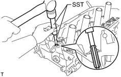
(c) Using SST and a hammer, tap out the valve guide bush. SST: 09201-10000 09201-01050 SST: 09950-70010 09951-07100 |
|
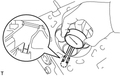
(d) Using a caliper gauge, measure the bush bore diameter of the cylinder head side. Standard bush bore diameter: 10.285 to 10.306 mm (0.405 to 0.406 in.) If the bush bore diameter of the cylinder head is between 10.285 and 10.306 mm (0.405 and 0.406 in.), proceed to the next step. If the bush bore diameter of the cylinder head is 10.356 mm (0.408 in.) or more, replace the cylinder head. |
(e) Select a new guide bush (STD or O/S 0.05), and measure its diameter.
(f) Machine the bush bore diameter of the cylinder head side to the diameter of the selected guide bush.
Bush Bore Diameter:
|
Bush Size |
Specified Condition |
|---|---|
|
STD |
10.333 to 10.344 mm (0.4068 to 0.4072 in.) |
|
O/S 0.05 |
10.383 to 10.394 mm (0.4088 to 0.4092 in.) |
Standard bush length:
41.3 to 41.7 mm (1.63 to 1.64 in.)
|
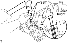
(g) Using SST and a hammer, tap in a new guide bush to the standard protrusion height. SST: 09201-10000 09201-01050 SST: 09950-70010 09951-07100 Standard protrusion height: 14.3 to 14.7 mm (0.563 to 0.579 in.) |
|
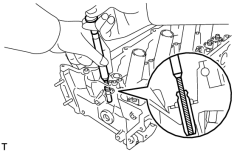
(h) Using a sharp 5.5 mm reamer, ream the guide bush to obtain the standard oil clearance between the guide bush and valve stem. Standard oil clearance: 0.025 to 0.060 mm (0.000984 to 0.00236 in.) |
2. REPLACE EXHAUST VALVE GUIDE BUSH
(a) Heat the cylinder head to approximately 80 to 100°C (176 to 212°F).
(b) Place the cylinder head on wooden blocks.
|
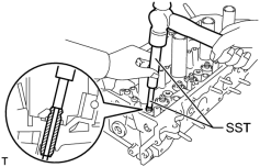
(c) Using SST and a hammer, tap out the valve guide bush. SST: 09201-10000 09201-01050 SST: 09950-70010 09951-07100 |
|
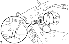
(d) Using a caliper gauge, measure the bush bore diameter of the cylinder head. Standard bush bore diameter: 10.285 to 10.306 mm (0.405 to 0.406 in.) If the bush bore diameter of the cylinder head is between 10.285 and 10.306 mm (0.405 and 0.406 in.), proceed to the next step. If the bush bore diameter of the cylinder head is 10.356 mm (0.408 in.) or more, replace the cylinder head. |
(e) Select a new guide bush (STD or O/S 0.05), and measure its diameter.
(f) Machine the bush bore diameter of the cylinder head side to the diameter of the selected guide bush.
Bush Bore Diameter:
|
Bush Size |
Specified Condition |
|---|---|
|
STD |
10.333 to 10.344 mm (0.4068 to 0.4072 in.) |
|
O/S 0.05 |
10.383 to 10.394 mm (0.4088 to 0.4092 in.) |
Standard bush length:
46.8 to 47.2 mm (1.84 to 1.86 in.)
|
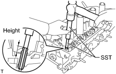
(g) Using SST and a hammer, tap in a new guide bush to the standard protrusion height. SST: 09201-10000 09201-01050 SST: 09950-70010 09951-07100 Standard protrusion height: 14.3 to 14.7 mm (0.563 to 0.579 in.) |
|
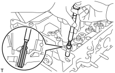
(h) Using a sharp 5.5 mm reamer, ream the guide bush to obtain the standard oil clearance between the guide bush and valve stem. Standard oil clearance: 0.030 to 0.065 mm (0.00118 to 0.00256 in.) |
3. REPLACE SPARK PLUG TUBE
HINT:
When using a new cylinder head, the spark plug tubes must be replaced.
(a) Remove the spark plug tube.
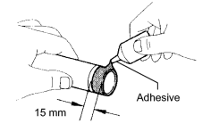
(b) Apply adhesive to the end of a new spark plug tube.
Adhesive:
Toyota Genuine Adhesive 1324, Three Bond 1324 or equivalent.
Standard seal diameter:
15 mm (0.591 in.)
NOTICE:
- Install the spark plug tube within 3 minutes after applying adhesive.
- Be careful not to deform the spark plug tube.
- Be careful not to expose the seal to coolant for at least 1 hour after installing it.
|
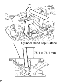
(c) Using a wooden block and hammer, tap in the spark plug tube to the specified protrusion height. Standard protrusion height: 75.1 to 76.1 mm (2.96 to 3.00 in.) NOTICE:
To avoid tapping in the spark plug tube too far, measure the protrusion height while tapping it. |
4. REPLACE RING PIN
NOTICE:
It is not necessary to remove the ring pin unless it is being replaced.
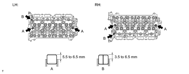
(a) Remove the ring pins.
(b) Using a plastic-faced hammer, tap in new ring pins to the cylinder head.
Standard Protrusion:
|
Item |
Specified Condition |
|---|---|
|
Ring pin A |
5.5 to 6.5 mm (0.217 to 0.256 in.) |
|
Ring pin B |
3.5 to 6.5 mm (0.138 to 0.256 in.) |

|

|