| Last Modified: 11-27-2007 | 1.6 A | |
| Service Category: Engine/Hybrid System | Section: Engine Mechanical | |
| Model Year: 2008 | Model: LX570 | Doc ID: RM000002OP900EX |
| Title: 3UR-FE ENGINE MECHANICAL: CYLINDER HEAD: REASSEMBLY (2008 LX570) | ||
REASSEMBLY
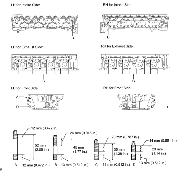
1. INSTALL STUD BOLT
(a) Using E7 and E8 "TORX" socket wrenches, install the stud bolts.
Torque: 9.0 N·m (92 kgf·cm, 80 in·lbf)
2. INSTALL NO. 2 STRAIGHT SCREW PLUG
|
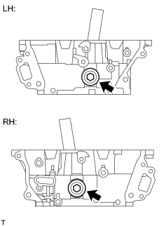
(a) Using a 14 mm hexagon wrench, install 2 new gaskets and the 2 straight screw plugs. Torque: 85 N·m (867 kgf·cm, 63 ft·lbf) |
3. INSTALL NO. 1 STRAIGHT SCREW PLUG
|
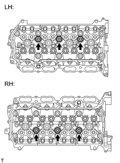
(a) Using a 10 mm hexagon wrench, install 6 new gaskets and the 6 straight screw plugs. Torque: 44 N·m (449 kgf·cm, 32 ft·lbf) |
4. INSTALL VALVE SPRING SEAT
(a) Install the valve spring seats to the cylinder head.
5. INSTALL VALVE STEM OIL SEAL
|
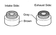
(a) Apply a light coat of engine oil to new oil seals. NOTICE:
Pay attention when installing the intake and exhaust oil seals. For example, installing the intake oil seal into the exhaust side or installing the exhaust oil seal into the intake side can cause installation problems later. HINT:
The intake valve oil seals are brown and the exhaust valve oil seals are gray. |
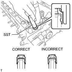
|
(b) Using SST, push in the oil seals. SST: 09201-41020 NOTICE:
Failure to use SST will cause the seal to be damaged or improperly seated. |
6. INSTALL INTAKE VALVE
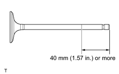
|
(a) Apply plenty of engine oil to the tip area of the intake valve shown in the illustration. |
(b) Install the valve, compression spring and spring retainer to the cylinder head.
NOTICE:
Install the same parts in the same combination to their original locations.
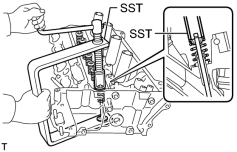
|
(c) Using SST and wooden blocks, compress the spring and install the retainer locks. SST: 09202-70020 09202-00010 09202-01010 09202-01020 |
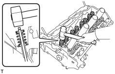
|
(d) Using a plastic-faced hammer, lightly tap the valve stem tip to ensure a proper fit. NOTICE:
Be careful not to damage the retainer. |
7. INSTALL EXHAUST VALVE
|
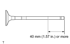
(a) Apply plenty of engine oil to the tip area of the exhaust valve shown in the illustration. |
(b) Install the valve, compression spring and spring retainer to the cylinder head.
NOTICE:
Install the same parts in the same combination to their original locations.
|
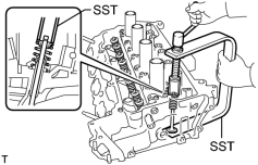
(c) Using SST and wooden blocks, compress the spring and install the retainer locks. SST: 09202-70020 09202-00010 09202-01010 09202-01020 |
|
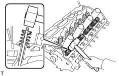
(d) Using a plastic-faced hammer, lightly tap the valve stem tip to ensure a proper fit. NOTICE:
Be careful not to damage the retainer. |

|

|