- The center airbag sensor receives a line short circuit signal, an open circuit signal, a short circuit to ground signal or a short circuit to B+ signal in the circuit for the side collision sensor RH (to determine deployment of the front seat side airbag RH and curtain shield airbag RH) for 2 seconds.
- A side airbag sensor RH malfunction.
- A rear airbag sensor RH malfunction.
- A center airbag sensor malfunction.
| Last Modified: 11-27-2007 | 1.6 C | |
| Service Category: Vehicle Interior | Section: Supplemental Restraint Systems | |
| Model Year: 2008 | Model: LX570 | Doc ID: RM000002P5E00LX |
| Title: SUPPLEMENTAL RESTRAINT SYSTEMS: AIRBAG SYSTEM: DESCRIPTION (2008 LX570) | ||
|
DTC |
B1642/81 |
Lost Communication with Side Satellite Sensor Bus RH |
|
DTC |
B1647/82 |
Lost Communication with Side Satellite Sensor Bus LH |
DESCRIPTION
The circuit for the side collision sensor LH or RH (to determine deployment of the front seat side airbag LH or RH, rear seat side airbag LH or RH, and curtain shield airbag LH or RH) is composed of the center airbag sensor, side airbag sensor LH or RH, and rear airbag sensor LH or RH.
The side airbag sensor LH or RH, and rear airbag sensor LH or RH detect impacts to the vehicle and send signals to the center airbag sensor to determine if the airbag should be deployed.
DTC B1642/81 or B1647/82 is stored when a malfunction is detected in the circuit for the side collision sensor LH or RH (to determine deployment of the front seat side airbag LH or RH, rear seat side airbag LH or RH and curtain shield airbag LH or RH).
|
DTC Code |
DTC Detection Condition |
Trouble Area |
|---|---|---|
|
B1642/81 |
When one of the following conditions is met: |
|
|
B1647/82 |
When one of the following conditions is met:
|
|
WIRING DIAGRAM
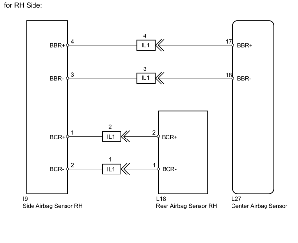
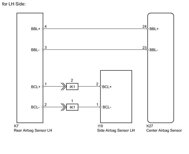
INSPECTION PROCEDURE
NOTICE:
-
w/ Navigation system:
After the engine switch is turned off, the HDD navigation system requires approximately 6 minutes to record various types of memory and settings. As a result, after turning the engine switch off, wait 6 minutes or more before disconnecting the cable from the negative (-) battery terminal.
-
When disconnecting the cable from the negative (-) battery terminal while performing repairs, some systems need to be initialized after the cable is reconnected
 .
.
PROCEDURE
|
1. |
CHECK FOR DTC |
(a) Turn the engine switch off.
(b) Turn the engine switch on (IG), and wait for at least 60 seconds.
(c) Check for DTCs
.
Result
|
Result |
Proceed to |
|---|---|
|
DTC B1642 and B1647 are not output |
A |
|
DTC B1647 is output |
B |
|
DTC B1642 is output |
C |
HINT:
Codes other than DTC B1642 and B1647 may be output at this time, but they are not related to this check.
|

|
2. |
CHECK CONNECTION OF CONNECTORS |
(a) Turn the engine switch off.
(b) Disconnect the cable from the negative (-) battery terminal, and wait for at least 90 seconds.
(c) Check that the connectors are properly connected to the center airbag sensor and side airbag sensor RH.
OK:
The connectors are properly connected.
|
|
3. |
CHECK CONNECTORS |
(a) Disconnect the connectors from the center airbag sensor and side airbag sensor RH.
(b) Check that the connectors (on the center airbag sensor side and side airbag sensor RH side) are not damaged.
OK:
The connectors are not deformed or damaged.
|
|
4. |
CHECK SIDE AIRBAG SENSOR RH CIRCUIT |
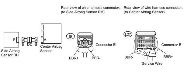
(a) Connect the cable to the negative (-) battery terminal, and wait for at least 2 seconds.
(b) Measure the voltage according to the value(s) in the table below.
Standard Voltage:
|
Tester Connection |
Switch Condition |
Specified Condition |
|---|---|---|
|
I9-4 (BBR+) - Body ground |
Engine switch on (IG) |
Below 1 V |
|
I9-3 (BBR-) - Body ground |
Engine switch on (IG) |
Below 1 V |
(c) Turn the engine switch off.
(d) Disconnect the cable from the negative (-) battery terminal, and wait for at least 90 seconds.
(e) Using a service wire, connect terminals 17 (BBR+) and 18 (BBR-) of connector B.
NOTICE:
Do not forcibly insert the service wire into the terminals of the connector when connecting a service wire.
(f) Measure the resistance according to the value(s) in the table below.
Standard Resistance:
|
Tester Connection |
Condition |
Specified Condition |
|---|---|---|
|
I9-4 (BBR+) - I9-3 (BBR-) |
Always |
Below 1 Ω |
(g) Disconnect the service wire from connector B.
(h) Measure the resistance according to the value(s) in the table below.
Standard Resistance:
|
Tester Connection |
Condition |
Specified Condition |
|---|---|---|
|
I9-4 (BBR+) - I9-3 (BBR-) |
Always |
1 MΩ or higher |
|
I9-4 (BBR+) - Body ground |
Always |
1 MΩ or higher |
|
I9-3 (BBR-) - Body ground |
Always |
1 MΩ or higher |
|
|
5. |
CHECK CONNECTION OF CONNECTORS |
(a) Check that the connector is properly connected to the rear airbag sensor RH.
OK:
The connector is properly connected.
|
|
6. |
CHECK CONNECTORS |
(a) Disconnect the connectors from the side airbag sensor RH and rear airbag sensor RH.
(b) Check that the connector (on the rear airbag sensor RH side) is not damaged.
OK:
The connector is not deformed or damaged.
|
|
7. |
CHECK REAR AIRBAG SENSOR RH CIRCUIT |
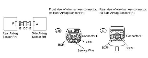
(a) Connect the cable to the negative (-) battery terminal, and wait for at least 2 seconds.
(b) Measure the voltage according to the value(s) in the table below.
Standard Voltage:
|
Tester Connection |
Switch Condition |
Specified Condition |
|---|---|---|
|
I9-1 (BCR+) - Body ground |
Engine switch on (IG) |
Below 1 V |
|
I9-2 (BCR-) - Body ground |
Engine switch on (IG) |
Below 1 V |
(c) Turn the engine switch off.
(d) Disconnect the cable from the negative (-) battery terminal, and wait for at least 90 seconds.
(e) Using a service wire, connect terminals 2 (BCR+) and 1 (BCR-) of connector E.
NOTICE:
Do not forcibly insert the service wire into the terminals of the connector when connecting a service wire.
(f) Measure the resistance according to the value(s) in the table below.
Standard Resistance:
|
Tester Connection |
Condition |
Specified Condition |
|---|---|---|
|
I9-1 (BCR+) - I9-2 (BCR-) |
Always |
Below 1 Ω |
(g) Disconnect the service wire from connector E.
(h) Measure the resistance according to the value(s) in the table below.
Standard Resistance:
|
Tester Connection |
Condition |
Specified Condition |
|---|---|---|
|
I9-1 (BCR+) - I9-2 (BCR-) |
Always |
1 MΩ or higher |
|
I9-1 (BCR+) - Body ground |
Always |
1 MΩ or higher |
|
I9-2 (BCR-) - Body ground |
Always |
1 MΩ or higher |
|
|
8. |
CHECK SIDE AIRBAG SENSOR RH |
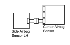
(a) Connect the connector to the center airbag sensor.
(b) Interchange the side airbag sensor LH with RH and connect the connectors to them.
(c) Connect the cable to the negative (-) battery terminal, and wait for at least 2 seconds.
(d) Turn the engine switch on (IG), and wait for at least 60 seconds.
(e) Clear the DTCs stored in the memory
.
(f) Turn the engine switch off.
(g) Turn the engine switch on (IG), and wait for at least 90 seconds.
(h) Check for DTCs
.
Result
|
Result |
Proceed to |
|---|---|
|
DTC B1642 and B1647 are not output |
A |
|
DTC B1647 is output |
B |
|
DTC B1642 is output |
C |
HINT:
Codes other than DTC B1642 and B1647 may be output at this time, but they are not related to this check.
(i) Turn the engine switch off.
(j) Disconnect the cable from the negative (-) battery terminal, and wait for at least 90 seconds.
(k) Return the side airbag sensor LH and RH to their original positions and connect the connectors to them.
|
|
9. |
CHECK REAR AIRBAG SENSOR RH |
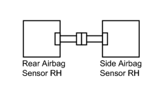
(a) Temporarily replace the rear airbag sensor RH with a new one.
(b) Connect the cable to the negative (-) battery terminal, and wait for at least 2 seconds.
(c) Turn the engine switch on (IG), and wait for at least 60 seconds.
(d) Clear the DTCs stored in the memory
.
(e) Turn the engine switch off.
(f) Turn the engine switch on (IG), and wait for at least 90 seconds.
(g) Check for DTCs
.
OK:
DTC B1642 is not output.
HINT:
Codes other than DTC B1642 may be output at this time, but they are not related to this check.
(h) Turn the engine switch off.
(i) Disconnect the cable from the negative (-) battery terminal, and wait for at least 90 seconds.
|
|
10. |
CHECK NO. 2 FLOOR WIRE (CENTER AIRBAG SENSOR - FRONT DOOR WIRE RH) |
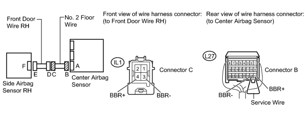
(a) Disconnect the No. 2 floor wire connector from the front door wire RH.
(b) Connect the cable to the negative (-) battery terminal, and wait for at least 2 seconds.
(c) Measure the voltage according to the value(s) in the table below.
Standard Voltage:
|
Tester Connection |
Switch Condition |
Specified Condition |
|---|---|---|
|
IL1-4 (BBR+) - Body ground |
Engine switch on (IG) |
Below 1 V |
|
IL1-3 (BBR-) - Body ground |
Engine switch on (IG) |
Below 1 V |
(d) Turn the engine switch off.
(e) Disconnect the cable from the negative (-) battery terminal, and wait for at least 90 seconds.
(f) Using a service wire, connect terminals 17 (BBR+) and 18 (BBR-) of connector B.
NOTICE:
Do not forcibly insert the service wire into the terminals of the connector when connecting a service wire.
(g) Measure the resistance according to the value(s) in the table below.
Standard Resistance:
|
Tester Connection |
Condition |
Specified Condition |
|---|---|---|
|
IL1-4 (BBR+) - IL1-3 (BBR-) |
Always |
Below 1 Ω |
(h) Disconnect the service wire from connector B.
(i) Measure the resistance according to the value(s) in the table below.
Standard Resistance:
|
Tester Connection |
Condition |
Specified Condition |
|---|---|---|
|
IL1-4 (BBR+) - IL1-3 (BBR-) |
Always |
1 MΩ or higher |
|
IL1-4 (BBR+) - Body ground |
Always |
1 MΩ or higher |
|
IL1-3 (BBR-) - Body ground |
Always |
1 MΩ or higher |
|
|
11. |
CHECK FRONT DOOR WIRE RH (SIDE AIRBAG SENSOR RH - NO. 2 FLOOR WIRE) |
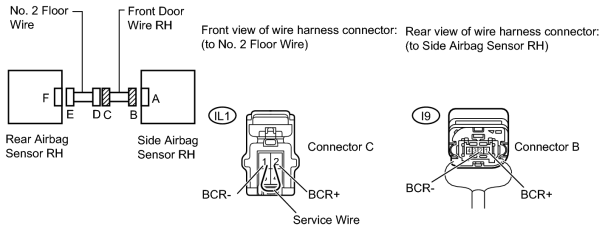
(a) Disconnect the front door wire RH connector from the No. 2 floor wire.
(b) Connect the cable to the negative (-) battery terminal, and wait for at least 2 seconds.
(c) Measure the voltage according to the value(s) in the table below.
Standard Voltage:
|
Tester Connection |
Switch Condition |
Specified Condition |
|---|---|---|
|
I9-1 (BCR+) - Body ground |
Engine switch on (IG) |
Below 1 V |
|
I9-2 (BCR-) - Body ground |
Engine switch on (IG) |
Below 1 V |
(d) Turn the engine switch off.
(e) Disconnect the cable from the negative (-) battery terminal, and wait for at least 90 seconds.
(f) Using a service wire, connect terminals 2 (BCR+) and 1 (BCR-) of connector C.
NOTICE:
Do not forcibly insert the service wire into the terminals of the connector when connecting a service wire.
(g) Measure the resistance according to the value(s) in the table below.
Standard Resistance:
|
Tester Connection |
Condition |
Specified Condition |
|---|---|---|
|
I9-1 (BCR+) - I9-2 (BCR-) |
Always |
Below 1 Ω |
(h) Disconnect the service wire from connector C.
(i) Measure the resistance according to the value(s) in the table below.
Standard Resistance:
|
Tester Connection |
Condition |
Specified Condition |
|---|---|---|
|
I9-1 (BCR+) - I9-2 (BCR-) |
Always |
1 MΩ or higher |
|
I9-1 (BCR+) - Body ground |
Always |
1 MΩ or higher |
|
I9-2 (BCR-) - Body ground |
Always |
1 MΩ or higher |
|
|
12. |
CHECK CONNECTION OF CONNECTORS |
(a) Turn the engine switch off.
(b) Disconnect the cable from the negative (-) battery terminal, and wait for at least 90 seconds.
(c) Check that the connectors are properly connected to the center airbag sensor and rear airbag sensor LH.
OK:
The connectors are properly connected.
|
|
13. |
CHECK CONNECTORS |
(a) Disconnect the connectors from the center airbag sensor and rear airbag sensor LH.
(b) Check that the connectors (on the center airbag sensor side and rear airbag sensor LH side) are not damaged.
OK:
The connectors are not deformed or damaged.
|
|
14. |
CHECK FLOOR WIRE (CENTER AIRBAG SENSOR - REAR AIRBAG SENSOR LH) |
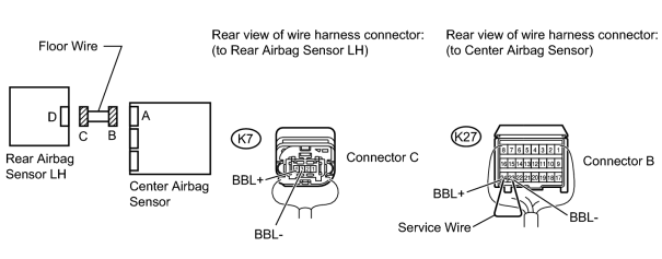
(a) Connect the cable to the negative (-) battery terminal, and wait for at least 2 seconds.
(b) Measure the voltage according to the value(s) in the table below.
Standard Voltage:
|
Tester Connection |
Switch Condition |
Specified Condition |
|---|---|---|
|
K7-4 (BBL+) - Body ground |
Engine switch on (IG) |
Below 1 V |
|
K7-3 (BBL-) - Body ground |
Engine switch on (IG) |
Below 1 V |
(c) Turn the engine switch off.
(d) Disconnect the cable from the negative (-) battery terminal, and wait for at least 90 seconds.
(e) Using a service wire, connect terminals 24 (BBL+) and 23 (BBL-) of connector B.
NOTICE:
Do not forcibly insert the service wire into the terminals of the connector when connecting a service wire.
(f) Measure the resistance according to the value(s) in the table below.
Standard Resistance:
|
Tester Connection |
Condition |
Specified Condition |
|---|---|---|
|
K7-4 (BBL+) - K7-3 (BBL-) |
Always |
Below 1 Ω |
(g) Disconnect the service wire from connector B.
(h) Measure the resistance according to the value(s) in the table below.
Standard Resistance:
|
Tester Connection |
Condition |
Specified Condition |
|---|---|---|
|
K7-4 (BBL+) - K7-3 (BBL-) |
Always |
1 MΩ or higher |
|
K7-4 (BBL+) - Body ground |
Always |
1 MΩ or higher |
|
K7-3 (BBL-) - Body ground |
Always |
1 MΩ or higher |
|
|
15. |
CHECK CONNECTION OF CONNECTOR |
(a) Check that the connector is properly connected to the side airbag sensor LH.
OK:
The connector is properly connected.
|
|
16. |
CHECK CONNECTORS |
(a) Disconnect the connectors from the rear airbag sensor LH and side airbag sensor LH.
(b) Check that the connector (on the side airbag sensor LH side) is not damaged.
OK:
The connector is not deformed or damaged.
|
|
17. |
CHECK SIDE AIRBAG SENSOR LH CIRCUIT |
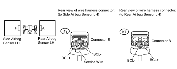
(a) Connect the cable to the negative (-) battery terminal, and wait for at least 2 seconds.
(b) Measure the voltage according to the value(s) in the table below.
Standard Voltage:
|
Tester Connection |
Switch Condition |
Specified Condition |
|---|---|---|
|
K7-1 (BCL+) - Body ground |
Engine switch on (IG) |
Below 1 V |
|
K7-2 (BCL-) - Body ground |
Engine switch on (IG) |
Below 1 V |
(c) Turn the engine switch off.
(d) Disconnect the cable from the negative (-) battery terminal, and wait for at least 90 seconds.
(e) Using a service wire, connect terminals 2 (BCL+) and 1 (BCL-) of connector E.
NOTICE:
Do not forcibly insert the service wire into the terminals of the connector when connecting a service wire.
(f) Measure the resistance according to the value(s) in the table below.
Standard Resistance:
|
Tester Connection |
Condition |
Specified Condition |
|---|---|---|
|
K7-1 (BCL+) - K7-2 (BCL-) |
Always |
Below 1 Ω |
(g) Disconnect the service wire from connector E.
(h) Measure the resistance according to the value(s) in the table below.
Standard Resistance:
|
Tester Connection |
Condition |
Specified Condition |
|---|---|---|
|
K7-1 (BCL+) - K7-2 (BCL-) |
Always |
1 MΩ or higher |
|
K7-1 (BCL+) - Body ground |
Always |
1 MΩ or higher |
|
K7-2 (BCL-) - Body ground |
Always |
1 MΩ or higher |
|
|
18. |
CHECK REAR AIRBAG SENSOR LH |
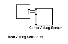
(a) Connect the connectors to the center airbag sensor.
(b) Temporarily replace the side airbag sensor LH with a new one.
(c) Connect the cable to the negative (-) battery terminal, and wait for at least 2 seconds.
(d) Turn the engine switch on (IG), and wait for at least 60 seconds.
(e) Clear the DTCs stored in the memory
.
(f) Turn the engine switch off.
(g) Turn the engine switch on (IG), and wait for at least 90 seconds.
(h) Check for DTCs
.
OK:
DTC B1642 or B1647 is not output.
HINT:
Codes other than DTC B1642 and B1647 may be output at this time, but they are not related to this check.
|
|
19. |
CHECK SIDE AIRBAG SENSOR LH |
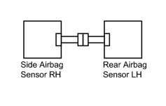
(a) Turn the engine switch off.
(b) Disconnect the cable from the negative (-) battery terminal, and wait for at least 90 seconds.
(c) Interchange the side airbag sensor RH with LH and connect the connectors to them.
(d) Connect the cable to the negative (-) battery terminal, and wait for at least 2 seconds.
(e) Turn the engine switch on (IG), and wait for at least 60 seconds.
(f) Clear the DTCs stored in the memory
.
(g) Turn the engine switch off.
(h) Turn the engine switch on (IG), and wait for at least 90 seconds.
(i) Check for DTCs
.
Result
|
Result |
Proceed to |
|---|---|
|
DTC B1647 is output |
A |
|
DTC B1642 is output |
B |
|
DTC B1642 and B1647 are not output |
C |
HINT:
Codes other than DTC B1642 and B1647 may be output at this time, but they are not related to this check.
(j) Turn the engine switch off.
(k) Disconnect the cable from the negative (-) battery terminal, and wait for at least 90 seconds.
(l) Return the rear airbag sensor RH and LH to their original positions and connect the connectors to them.
|
|
20. |
CHECK FLOOR WIRE (REAR SIDE AIRBAG SENSOR LH - FRONT DOOR WIRE LH) |
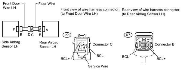
(a) Disconnect the floor wire connector from the front door wire LH.
(b) Connect the cable to the negative (-) battery terminal, and wait for at least 2 seconds.
(c) Measure the voltage according to the value(s) in the table below.
Standard Voltage:
|
Tester Connection |
Switch Condition |
Specified Condition |
|---|---|---|
|
K7-1 (BCL+) - Body ground |
Engine switch on (IG) |
Below 1 V |
|
K7-2 (BCL-) - Body ground |
Engine switch on (IG) |
Below 1 V |
(d) Turn the engine switch off.
(e) Disconnect the cable from the negative (-) battery terminal, and wait for at least 90 seconds.
(f) Using a service wire, connect terminals 2 (BCL+) and 1 (BCL-) of connector C.
NOTICE:
Do not forcibly insert the service wire into the terminals of the connector when connecting a service wire.
(g) Measure the resistance according to the value(s) in the table below.
Standard Resistance:
|
Tester Connection |
Condition |
Specified Condition |
|---|---|---|
|
K7-1 (BCL+) - K7-2 (BCL-) |
Always |
Below 1 Ω |
(h) Disconnect the service wire from connector C.
(i) Measure the resistance according to the value(s) in the table below.
Standard Resistance:
|
Tester Connection |
Condition |
Specified Condition |
|---|---|---|
|
K7-1 (BCL+) - K7-2 (BCL-) |
Always |
1 MΩ or higher |
|
K7-1 (BCL+) - Body ground |
Always |
1 MΩ or higher |
|
K7-2 (BCL-) - Body ground |
Always |
1 MΩ or higher |
|

|

|