- Seat climate control controller
- Seat climate control ECU
- Harness or connector
| Last Modified: 11-27-2007 | 1.6 C | |
| Service Category: Vehicle Interior | Section: Seat | |
| Model Year: 2008 | Model: LX570 | Doc ID: RM000002RD0005X |
| Title: SEAT: CLIMATE CONTROL SEAT SYSTEM: DESCRIPTION (2008 LX570) | ||
|
DTC |
B14F1 |
Seatback Peltier Temperature Sensor Malfunction |
DESCRIPTION
Outputs to the seat climate control controller stop if one of the following occurs: 1) the seat climate control controller temperature sensor is open or shorted; 2) the temperature sensor is damaged and its output value does not change.
|
DTC Code |
DTC Detection Condition |
Trouble Area |
|---|---|---|
|
B14F1 |
Seatback peltier temperature sensor malfunction. |
|
WIRING DIAGRAM
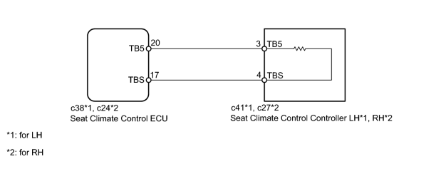
INSPECTION PROCEDURE
PROCEDURE
|
1. |
CHECK FOR DTC |
(a) Check for DTCs
 .
.
Result
|
Result |
Proceed to |
|---|---|
|
DTC is output (Driver seat climate control ECU) |
A |
|
DTC is output (Passenger seat climate control ECU) |
B |
|

|
2. |
READ VALUE USING TECHSTREAM (SEATBACK TEMPERATURE SENSOR) |
(a) Check the Data List for proper functioning of the temperature sensor.
Front Left Seat A/C
|
Item |
Measurement Item/Range |
Normal Condition |
Diagnostic Note |
|---|---|---|---|
|
Seatback Temp |
Seatback temperature sensor signal / MIN: 0°C (32°F), MAX: 85°C (185°F) |
Within range from 0 to 85°C (32 to 185°F) |
- |
OK:
The display is as specified in the normal condition.
|
|
3. |
INSPECT SEAT CLIMATE CONTROL CONTROLLER LH |
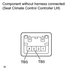
(a) Disconnect the c41 climate control controller connector.
(b) Measure the resistance according to the value(s) in the table below.
Standard Resistance:
|
Tester Connection |
Condition |
Specified Condition |
|---|---|---|
|
3 (TB5) - 4 (TBS) |
Outside air temperature 10 to 30°C (50 to 86°F) |
1.85 to 0.8 kΩ |
|
|
4. |
CHECK HARNESS AND CONNECTOR (SEAT CLIMATE CONTROL ECU - SEAT CLIMATE CONTROL CONTROLLER LH) |
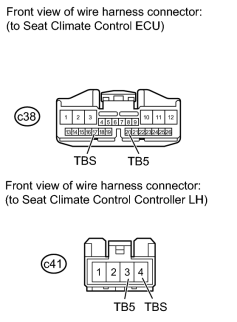
(a) Disconnect the c38 ECU connector.
(b) Disconnect the c41 climate control controller connector.
(c) Measure the resistance according to the value(s) in the table below.
Standard Resistance:
|
Tester Connection |
Condition |
Specified Condition |
|---|---|---|
|
c38-20 (TB5) - c41-3 (TB5) |
Always |
Below 1 Ω |
|
c38-17 (TBS) - c41-4 (TBS) |
Always |
Below 1 Ω |
|
c38-20 (TB5) - Body ground |
Always |
10 kΩ or higher |
|
c38-17 (TBS) - Body ground |
Always |
10 kΩ or higher |
|
|
5. |
READ VALUE USING TECHSTREAM (SEATBACK TEMPERATURE SENSOR) |
(a) Check the Data List for proper functioning of the temperature sensor.
Front Right Seat A/C
|
Item |
Measurement Item/Range |
Normal Condition |
Diagnostic Note |
|---|---|---|---|
|
Seatback Temp |
Seatback temperature sensor signal / MIN: 0°C (32°F), MAX: 85°C (185°F) |
Within range from 0 to 85°C (32 to 185°F) |
- |
OK:
The display is as specified in the normal condition.
|
|
6. |
INSPECT SEAT CLIMATE CONTROL CONTROLLER RH |
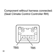
(a) Disconnect the c27 climate control controller connector.
(b) Measure the resistance according to the value(s) in the table below.
Standard Resistance:
|
Tester Connection |
Condition |
Specified Condition |
|---|---|---|
|
3 (TB5) - 4 (TBS) |
Outside air temperature 10 to 30°C (50 to 86°F) |
1.85 to 0.8 kΩ |
|
|
7. |
CHECK HARNESS AND CONNECTOR (SEAT CLIMATE CONTROL ECU - SEAT CLIMATE CONTROL CONTROLLER RH) |
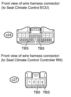
(a) Disconnect the c24 ECU connector.
(b) Disconnect the c27 climate control controller connector.
(c) Measure the resistance according to the value(s) in the table below.
Standard Resistance:
|
Tester Connection |
Condition |
Specified Condition |
|---|---|---|
|
c24-20 (TB5) - c27-3 (TB5) |
Always |
Below 1 Ω |
|
c24-17 (TBS) - c27-4 (TBS) |
Always |
Below 1 Ω |
|
c24-20 (TB5) - Body ground |
Always |
10 kΩ or higher |
|
c24-17 (TBS) - Body ground |
Always |
10 kΩ or higher |
|

|

|