- Master switch
- Main body ECU (cowl side junction block LH)
- Harness or connector
| Last Modified: 11-27-2007 | 1.6 C | |
| Service Category: Power Source/Network | Section: Networking | |
| Model Year: 2008 | Model: LX570 | Doc ID: RM000002S8B008X |
| Title: NETWORKING: LIN COMMUNICATION SYSTEM: DESCRIPTION (2008 LX570) | ||
|
DTC |
B1206 |
P/W Master Switch Communication Stop |
DESCRIPTION
This DTC is stored when LIN communication between the master switch and main body ECU (cowl side junction block LH) stops for 10 seconds or more.
|
DTC Code |
DTC Detection Condition |
Trouble Area |
|---|---|---|
|
B1206 |
No communication between the master switch and main body ECU (cowl side junction block LH) for 10 seconds or more. |
|
WIRING DIAGRAM
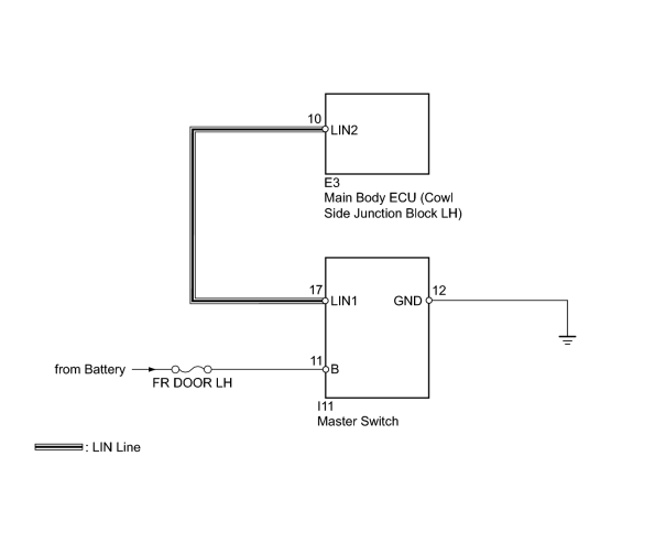
INSPECTION PROCEDURE
NOTICE:
When using the Techstream with the engine switch off to troubleshoot:
Connect the Techstream to the vehicle, and turn a courtesy switch on and off at 1.5 second intervals until communication between the Techstream and vehicle begins.
HINT:
DTC B2325 is stored when the communication between the master switch and main body ECU (cowl side junction block LH) stops.
PROCEDURE
|
1. |
CLEAR DTC |
(a) Clear the DTC
 .
.
|

|
2. |
CHECK FOR DTC |
(a) Recheck for DTCs
.
Result
|
Result |
Proceed to |
|---|---|
|
DTC B1206 is output |
A |
|
DTC B1206 is not output |
B |
|
|
3. |
CHECK HARNESS AND CONNECTOR (MAIN BODY ECU - MASTER SWITCH) |
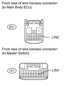
(a) Disconnect the E3 ECU connector.
(b) Disconnect the I11 switch connector.
(c) Measure the resistance and voltage according to the value(s) in the tables below.
Standard Resistance:
|
Tester Connection |
Condition |
Specified Condition |
|---|---|---|
|
E3-10 (LIN2) - N13-17 (LIN1) |
Always |
Below 1 Ω |
|
E3-10 (LIN2) or I11-17 (LIN1) - Body ground |
Always |
10 kΩ or higher |
Standard Voltage:
|
Tester Connection |
Condition |
Specified Condition |
|---|---|---|
|
I11-17 (LIN1) - Body ground |
Always |
Below 1 V |
|
|
4. |
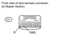
CHECK MASTER SWITCH ASSEMBLY (BATTERY VOLTAGE AND BODY GROUND) |
|
(a) Disconnect the I11 switch connector. |
(b) Measure the resistance and voltage according to the value(s) in the tables below.
Standard Resistance:
|
Tester Connection |
Condition |
Specified Condition |
|---|---|---|
|
I11-12 (GND) - Body ground |
Always |
Below 1 Ω |
Standard Voltage:
|
Tester Connection |
Condition |
Specified Condition |
|---|---|---|
|
I11-11 (B) - Body ground |
Always |
11 to 14 V |
|
|
5. |
REPLACE MASTER SWITCH ASSEMBLY |
(a) Temporarily replace the master switch assembly with a new or normally functioning one
.
(b) Clear the DTC
.
|
|
6. |
CHECK FOR DTC |
(a) Recheck for DTCs
.
Result
|
Result |
Proceed to |
|---|---|
|
DTC B1206 is not output |
A |
|
DTC B1206 is output |
B |
|

|

|