| Last Modified: 11-27-2007 | 1.6 J | |
| Service Category: Vehicle Exterior | Section: Lighting (ext) | |
| Model Year: 2008 | Model: LX570 | Doc ID: RM000002T2M007X |
| Title: LIGHTING (EXT): LIGHTING SYSTEM: WIRING DIAGRAM (2008 LX570) | ||
|
Clearance Light does not Illuminate |
WIRING DIAGRAM
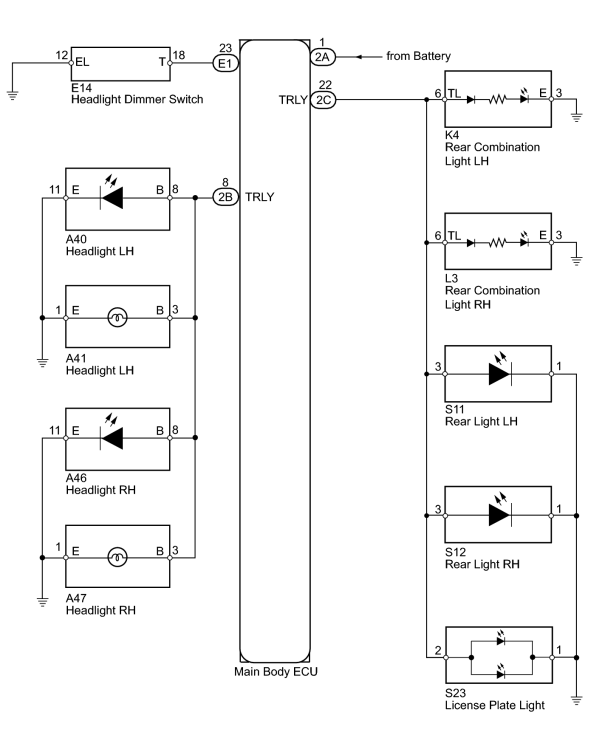
INSPECTION PROCEDURE
PROCEDURE
|
1. |
CHECK FOR DTC |
(a) Check for DTCs
 .
.
OK:
DTC B2402 output does not occur.
|

|
2. |
READ VALUE USING TECHSTREAM (HEADLIGHT DIMMER SWITCH) |
(a) Using the Techstream, read the Data List.
Main Body
|
Tester Display |
Measurement Item/Range |
Normal Condition |
Diagnostic Note |
|---|---|---|---|
|
Head Light SW (Tail) |
Headlight dimmer switch (Tail) signal/ON or OFF |
ON: Headlight dimmer switch (Tail) on OFF: Headlight dimmer switch off |
- |
OK:
When the headlight dimmer switch operation is performed, the result will be the same as above.
|
|
3. |
PERFORM ACTIVE TEST USING TECHSTREAM (TAILLIGHT) |
(a) Using the Techstream, perform the Active Test.
Main Body
|
Tester Display |
Test Part |
Control Range |
Diagnostic Note |
|---|---|---|---|
|
Taillight Relay |
Taillight |
ON or OFF |
- |
OK:
Taillight turns on/off.
|
|
4. |
INSPECT HEADLIGHT DIMMER SWITCH |
(a) Remove the headlight dimmer switch
.
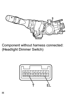
(b) Measure the resistance according to the value(s) in the table below.
Standard Resistance:
|
Tester Connection |
Condition |
Specified Condition |
|---|---|---|
|
18 (T) - 12 (EL) |
Headlight dimmer switch (Light control switch) tail |
Below 1 Ω |
|
18 (T) - 12 (EL) |
Headlight dimmer switch (Light control switch) off |
10 kΩ or higher |
|
|
5. |
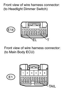
CHECK HARNESS AND CONNECTOR (HEADLIGHT DIMMER SWITCH - MAIN BODY ECU AND BODY GROUND) |
|
(a) Disconnect the E14 ECU connector. |
(b) Disconnect the E1 ECU connector.
(c) Measure the resistance according to the value(s) in the table below.
Standard Resistance:
|
Tester Connection |
Condition |
Specified Condition |
|---|---|---|
|
E14-18 (T) - E1-23 (TAIL) |
Always |
Below 1 Ω |
|
E14-12 (EL) - Body ground |
||
|
E14-18 (T) - Body ground |
Always |
10 kΩ or higher |
|
|
6. |
CHECK HARNESS AND CONNECTOR (MAIN BODY ECU - BODY GROUND) |
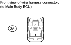
(a) Disconnect the 2A ECU connector.
(b) Measure the voltage according to the value(s) in the table below.
Standard Voltage:
|
Tester Connection |
Switch Condition |
Specified Condition |
|---|---|---|
|
2A-1 - Body ground |
Always |
11 to 14 V |
|
|
7. |
CHECK MAIN BODY ECU |
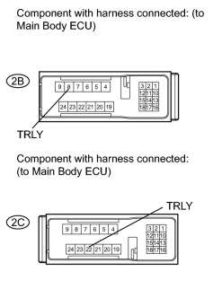
|
(a) Measure the voltage according to the value(s) in the table below. Standard Voltage:
|
|
|
8. |
CONFIRM LIGHT POSITION |
(a) Check the malfunctioning light.
Result
|
Result |
Proceed to |
|---|---|
|
Clearance light does not illuminate |
A |
|
Front side marker light does not illuminate |
B |
|
Rear side marker light does not illuminate |
C |
|
Taillight does not illuminate |
D |
|
License plate light does not illuminate |
E |
|
|
9. |
CHECK HARNESS AND CONNECTOR (HEADLIGHT - MAIN BODY ECU AND BODY GROUND) |
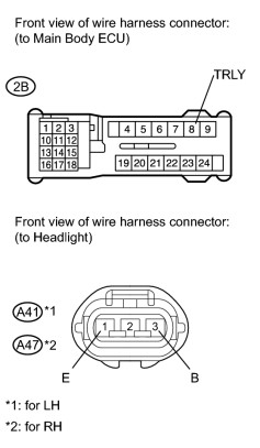
|
(a) Disconnect the 2B ECU connector. |
(b) Disconnect the A41 and A47 light connectors.
(c) Measure the resistance according to the value(s) in the table below.
Standard Resistance:
for LH
for RH
|
Tester Connection |
Condition |
Specified Condition |
|---|---|---|
|
2B-8 (TRLY) - A41-3 (B) |
Always |
Below 1 Ω |
|
A41-1 (E) - Body ground |
||
|
A41-3 (B) - Body ground |
Always |
10 kΩ or higher |
|
Tester Connection |
Condition |
Specified Condition |
|---|---|---|
|
2B-8 (TRLY) - A47-3 (B) |
Always |
Below 1 Ω |
|
A47-1 (E) - Body ground |
||
|
A47-3 (B) - Body ground |
Always |
10 kΩ or higher |
|
|
10. |
CHECK HARNESS AND CONNECTOR (HEADLIGHT - MAIN BODY ECU AND BODY GROUND) |
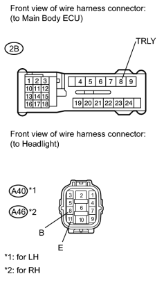
|
(a) Disconnect the 2B ECU connector. |
(b) Disconnect the A40 and A46 light connectors.
(c) Measure the resistance according to the value(s) in the table below.
Standard Resistance:
for LH
for RH
|
Tester Connection |
Condition |
Specified Condition |
|---|---|---|
|
2B-8 (TRLY) - A40-8 (B) |
Always |
Below 1 Ω |
|
A40-11 (E) - Body ground |
||
|
A40-8 (B) - Body ground |
Always |
10 kΩ or higher |
|
Tester Connection |
Condition |
Specified Condition |
|---|---|---|
|
2B-8 (TRLY) - A46-8 (B) |
Always |
Below 1 Ω |
|
A46-11 (E) - Body ground |
||
|
A46-8 (B) - Body ground |
Always |
10 kΩ or higher |
|
|
11. |
CHECK HARNESS AND CONNECTOR (REAR COMBINATION LIGHT - MAIN BODY ECU AND BODY GROUND) |
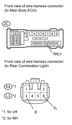
|
(a) Disconnect the 2C ECU connector. |
(b) Disconnect the K4 and L3 light connectors.
(c) Measure the resistance according to the value(s) in the table below.
Standard Resistance:
for LH
for RH
|
Tester Connection |
Condition |
Specified Condition |
|---|---|---|
|
2C-22 (TRLY) - K4-6 (TL) |
Always |
Below 1 Ω |
|
K4-3 (E) - Body ground |
||
|
K4-6 (TL) - Body ground |
Always |
10 kΩ or higher |
|
Tester Connection |
Condition |
Specified Condition |
|---|---|---|
|
2C-22 (TRLY) - L3-6 (TL) |
Always |
Below 1 Ω |
|
L3-3 (E) - Body ground |
||
|
L3-6 (TL) - Body ground |
Always |
10 kΩ or higher |
|
|
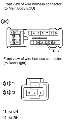
12. |
CHECK HARNESS AND CONNECTOR (REAR LIGHT - MAIN BODY ECU AND BODY GROUND) |
|
(a) Disconnect the 2C ECU connector. |
(b) Disconnect the S11 and S12 light connectors.
(c) Measure the resistance according to the value(s) in the table below.
Standard Resistance:
for LH
for RH
|
Tester Connection |
Condition |
Specified Condition |
|---|---|---|
|
2C-22 (TRLY) - S11-3 |
Always |
Below 1 Ω |
|
S11-1 - Body ground |
||
|
S11-3 - Body ground |
Always |
10 kΩ or higher |
|
Tester Connection |
Condition |
Specified Condition |
|---|---|---|
|
2C-22 (TRLY) - S12-3 |
Always |
Below 1 Ω |
|
S12-1 - Body ground |
||
|
S12-3 - Body ground |
Always |
10 kΩ or higher |
|
|
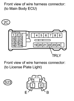
13. |
CHECK HARNESS AND CONNECTOR (LICENSE PLATE LIGHT - MAIN BODY ECU AND BODY GROUND) |
|
(a) Disconnect the 2C ECU connector. |
(b) Disconnect the S23 light connector.
(c) Measure the resistance according to the value(s) in the table below.
Standard Resistance:
|
Tester Connection |
Condition |
Specified Condition |
|---|---|---|
|
2C-22 (TRLY) - S23-2 |
Always |
Below 1 Ω |
|
S23-1 - Body ground |
||
|
S23-2 - Body ground |
Always |
10 kΩ or higher |
|

|

|