| Last Modified: 11-27-2007 | 1.6 J | |
| Service Category: Audio/Visual/Telematics | Section: Audio/Video | |
| Model Year: 2008 | Model: LX570 | Doc ID: RM000002TSI004X |
| Title: AUDIO / VIDEO: AUDIO AND VISUAL SYSTEM: DESCRIPTION (2008 LX570) | ||
|
Satellite Radio Tuner Power Source Circuit |
DESCRIPTION
This is the power source circuit to operate the stereo component tuner.
HINT:
- "Satellite Radio Tuner" refers to the stereo component tuner.
- Only vehicles with a navigation system have this circuit.
WIRING DIAGRAM
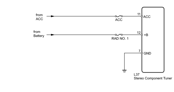
INSPECTION PROCEDURE
PROCEDURE
|
1. |
INSPECT FUSE (ACC, RAD NO. 1) |
(a) Remove the ACC fuse from the main body ECU.
(b) Remove the RAD NO. 1 fuse from the engine room relay block.
(c) Measure the resistance according to the value(s) in the table below.
Standard Resistance:
|
Tester Connection |
Condition |
Specified Condition |
|---|---|---|
|
ACC fuse |
Always |
Below 1 Ω |
|
RAD NO. 1 fuse |
Always |
Below 1 Ω |
|

|
2. |
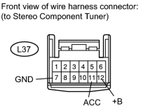
CHECK HARNESS AND CONNECTOR (STEREO COMPONENT TUNER - BATTERY AND BODY GROUND) |
|
(a) Disconnect the L37 tuner connector. |
(b) Measure the resistance according to the value(s) in the table below.
Standard Resistance:
|
Tester Connection |
Condition |
Specified Condition |
|---|---|---|
|
L37-7 (GND) - Body ground |
Always |
Below 1 Ω |
(c) Measure the voltage according to the value(s) in the table below.
Standard Voltage:
|
Tester Connection |
Condition |
Specified Condition |
|---|---|---|
|
L37-12 (+B) - L37-7 (GND) |
Always |
11 to 14 V |
|
L37-11 (ACC) - L37-7 (GND) |
Engine switch on (ACC) |
11 to 14 V |
|

|

|