| Last Modified: 11-27-2007 | 1.6 J | |
| Service Category: Audio/Visual/Telematics | Section: Navigation/Multi Info Display | |
| Model Year: 2008 | Model: LX570 | Doc ID: RM000002TUZ003X |
| Title: NAVIGATION / MULTI INFO DISPLAY: NAVIGATION SYSTEM: DESCRIPTION (2008 LX570) | ||
|
AVC-LAN Plus Circuit |
DESCRIPTION
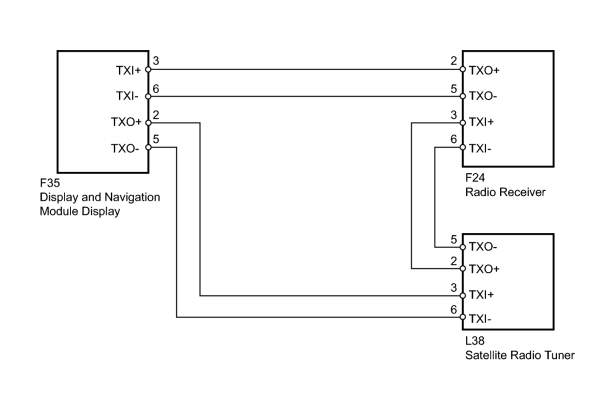
The navigation system uses AVC-LAN plus communication between components when performing sound library recording, and when displaying the satellite radio traffic information screen.
If a +B short, ground short, or other malfunction occurs in the AVC-LAN plus circuit, communication is stopped and the system does not operate normally.
WIRING DIAGRAM
INSPECTION PROCEDURE
NOTICE:
After replacing the satellite radio tuner of vehicles subscribed to pay-type satellite radio broadcasts, ID registration is necessary.
PROCEDURE
|
1. |
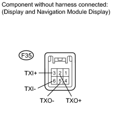
CHECK HARNESS AND CONNECTOR (DISPLAY AND NAVIGATION MODULE DISPLAY - RADIO RECEIVER AND SATELLITE RADIO TUNER) |
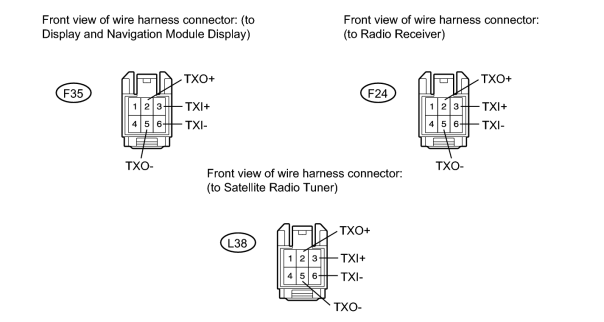
(a) Disconnect the F35 display connector.
(b) Disconnect the F24 receiver connector.
(c) Disconnect the L38 tuner connector.
(d) Measure the resistance according to the value(s) in the table below.
Standard Resistance:
|
Tester Connection |
Condition |
Specified Condition |
|---|---|---|
|
F35-3 (TXI+) - F24-2 (TXO+) |
Always |
Below 1 Ω |
|
F35-6 (TXI-) - F24-5 (TXO-) |
Always |
Below 1 Ω |
|
F35-2 (TXO+) - L38-3 (TXI+) |
Always |
Below 1 Ω |
|
F35-5 (TXO-) - L38-6 (TXI-) |
Always |
Below 1 Ω |
|
L38-2 (TXO+) - F24-3 (TXI+) |
Always |
Below 1 Ω |
|
L38-5 (TXO-) - F24-6 (TXI-) |
Always |
Below 1 Ω |
|
F35-3 (TXI+) - Body ground |
Always |
10 kΩ or higher |
|
F35-6 (TXI-) - Body ground |
Always |
10 kΩ or higher |
|
F35-2 (TXO+) - Body ground |
Always |
10 kΩ or higher |
|
F35-5 (TXO-) - Body ground |
Always |
10 kΩ or higher |
|
L38-2 (TXO+) - Body ground |
Always |
10 kΩ or higher |
|
L38-5 (TXO-) - Body ground |
Always |
10 kΩ or higher |
|

|
2. |
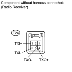
INSPECT RADIO RECEIVER ASSEMBLY |
|
(a) Measure the resistance according to the value(s) in the table below. Standard Resistance:
|
|
|
3. |
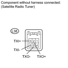
INSPECT SATELLITE RADIO TUNER |
|
(a) Measure the resistance according to the value(s) in the table below. Standard Resistance:
|
|
|
4. |
INSPECT DISPLAY AND NAVIGATION MODULE DISPLAY |
|
(a) Measure the resistance according to the value(s) in the table below. Standard Resistance:
|
|

|

|