- Throttle body
- Mass air flow meter
- PCV hose
- Air cleaner filter
- Air induction system
- VVT system
- ECM
| Last Modified: 11-27-2007 | 1.6 C | |
| Service Category: Engine/Hybrid System | Section: Engine Control | |
| Model Year: 2008 | Model: LX570 | Doc ID: RM000002U1300MX |
| Title: 3UR-FE ENGINE CONTROL: SFI SYSTEM: DESCRIPTION (2008 LX570) | ||
|
DTC |
P050A |
Cold Start Idle Air Control System Performance |
DESCRIPTION
|
DTC Code |
DTC Detection Condition |
Trouble Area |
|---|---|---|
|
P050A |
Mass air flow is insufficient at cold start (2 trip detection logic). |
|
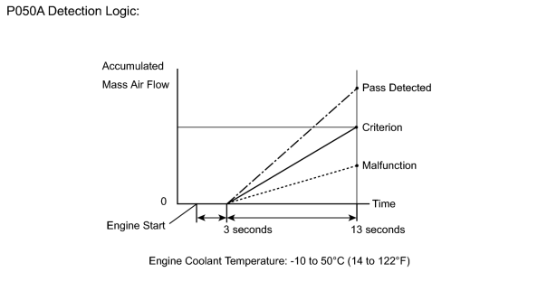
This monitor will run when the engine is started with the engine coolant temperature at -10 to 50°C (14 to 122°F). The DTC will be stored after the engine idles for 13 seconds (2 trip detection logic).
The DTC is designed to monitor the idle air control at cold start. When the engine is started with the engine coolant temperature at below 50°C (122°F), the ECM (PCM) measures the accumulated mass air flow at engine idling. If it does not reach the criteria within 10 seconds, the ECM (PCM) interprets this as a malfunction. The MIL is illuminated and a DTC is stored when the malfunction is detected in consecutive driving cycles (2 trip detection logic).
The ETCS (Electronic Throttle Control System) controls the idle speed. The ETCS operates the throttle actuator to open and close the throttle valve, and adjusts the intake air amount to achieve the target idle speed.
NOTICE:
When the cable is disconnected from the negative (-) battery terminal during inspections or repairs, the ISC (Idle Speed Control) learning values are cleared. This DTC cannot be stored with the ISC learning values cleared.
The ISC learning is performed when the engine is warmed up and has been idling for 5 minutes.
MONITOR STRATEGY
|
Related DTCs |
P050A: Cold start idle air speed control system |
|
Required sensors/Components (Main) |
Throttle body |
|
Required sensors/Components (Related) |
Mass air flow meter Engine coolant temperature sensor |
|
Frequency of operation |
Once per driving cycle |
|
Duration |
10 seconds |
|
MIL operation |
2 driving cycles |
|
Sequence of operation |
None |
TYPICAL ENABLING CONDITIONS
|
Battery voltage |
8 V or higher |
|
Time after engine start |
3 seconds or more |
|
Starter |
OFF |
|
ECT at engine start |
-10°C (14°F) or higher |
|
ECT |
-10 to 50°C (14 to 122°F) |
|
Engine idling |
3 seconds or more |
|
Fuel cut |
OFF |
|
Vehicle speed |
Less than 3 km/h (1.875 mph) |
|
Time after shift position changed |
2 seconds or more |
|
Atmospheric pressure |
76 kPa (570 mmHg) or higher |
TYPICAL MALFUNCTION THRESHOLDS
|
Accumulated mass air flow |
Less than 116 g (varies with ECT) |
INSPECTION PROCEDURE
HINT:
Read freeze frame data using the Techstream. Freeze frame data records the engine condition when malfunctions are detected. When troubleshooting, freeze frame data can help determine if the vehicle was moving or stationary, if the engine was warmed up or not, if the air-fuel ratio was lean or rich, and other data from the time the malfunction occurred.
PROCEDURE
|
1. |
CHECK DTCS |
OK:
Any other DTCs are not output.
|

|
2. |
READ VALUE USING TECHSTREAM (FUEL TRIM) |
HINT:
Calculate the total fuel trim values to check the characteristic deviation of the mass air flow meter.
(a) Connect the Techstream to the DLC3.
(b) Turn the engine switch on (IG) and turn the Techstream on.
(c) Enter the following menus: Powertrain / Engine and ECT / Data List / A/F Control System / Short FT #1 and Long FT #1, or Short FT #2 and Long FT #2.
(d) Read the values displayed on the Techstream.
(e) Add together the Short FT #1 and Long FT #1, or Short FT #2 and Long FT #2 values to obtain the total fuel trim.
Result:
Total of Short FT #1 and Long FT #1, or Short FT #2 and Long FT #2 values is between -20% and 20%.
|
|
3. |
CHECK THROTTLE BODY |
(a) Check for deposits around the throttle valve and throttle valve condition.
OK:
No deposits around throttle valve and throttle valve moves smoothly.
|
4. |
CHECK VVT SYSTEM |
(a) Allow the engine to idle after the engine is warmed up.
(b) Enter the following menus: Powertrain / Engine and ECT / Active Test / Control the VVT System (Bank 1) or Control the VVT System (Bank 2).
(c) Turn on Control the VVT System (Bank 1) or Control the VVT System (Bank 2) to advance the valve timing.
(d) Check the engine condition.
OK:
The engine stalls or idles roughly when Control the VVT System is ON (VVT system is OK).
|
|
5. |
CHECK PCV SYSTEM |
(a) Allow the engine to idle.
(b) Pinch the positive crankcase ventilation (PCV) hose.
(c) Check the engine speed.
OK:
The engine speed rises when the PCV hose is pinched.
|
|
6. |
CHECK AIR CLEANER FILTER |
(a) Visually check that the air cleaner filter is not excessively contaminated with dirt or oil.
|
|
7. |
CHECK AIR INDUCTION SYSTEM |
(a) Check the air induction system for vacuum leakage
 .
.
|
8. |
REPAIR OR REPLACE THROTTLE BODY |
(a) Repair or replace the throttle body
.
|
9. |
REPLACE ECM |
(a) Replace the ECM
.
|
10. |
CHECK AND REPAIR VVT SYSTEM |
|
11. |
REPAIR OR REPLACE PCV HOSE |
|
12. |
REPLACE AIR CLEANER FILTER |
|
13. |
REPAIR OR REPLACE AIR INDUCTION SYSTEM |
|
14. |
REPLACE MASS AIR FLOW METER |
(a) Replace the mass air flow meter
.
|
|
15. |
CHECK DTCS |
(a) Check that the engine coolant temperature is -10 to 50°C (14 to 122°F).
(b) Clear the DTC
.
(c) Enter the check mode using the Techstream
.
(d) Allow the engine to idle for 1 minute.
(e) Check that no DTC is output.
|

|

|