- Telephone ECU assembly
- Harness or connector
- Bus buffer ECU
| Last Modified: 11-27-2007 | 1.6 C | |
| Service Category: Audio/Visual/Telematics | Section: Cellular Communication | |
| Model Year: 2008 | Model: LX570 | Doc ID: RM000002UB5003X |
| Title: CELLULAR COMMUNICATION: LEXUS LINK SYSTEM: DESCRIPTION (2008 LX570) | ||
|
DTC |
U0198 |
Lost Communication with Telematic Control Module |
DESCRIPTION
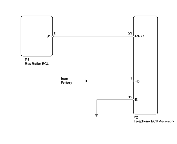
This DTC is stored when communication stops between the telephone ECU assembly and bus buffer ECU.
|
DTC Code |
DTC Detection Condition |
Trouble Area |
|---|---|---|
|
U0198 |
No signal from the telephone ECU assembly for more than 10 seconds. |
|
WIRING DIAGRAM
INSPECTION PROCEDURE
PROCEDURE
|
1. |
CHECK HARNESS AND CONNECTOR (COMMUNICATION LINE) |
|
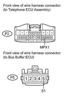
(a) Disconnect the P2 and P5 ECU connectors. |
(b) Measure the resistance according to the value(s) in the table below.
Standard Resistance:
|
Tester Connection |
Condition |
Specified Condition |
|---|---|---|
|
P2-23 (MPX1) - P5-5 (S1) |
Always |
Below 1 Ω |
|

|
2. |
CHECK HARNESS AND CONNECTOR (TELEPHONE ECU ASSEMBLY - VEHICLE BATTERY AND BODY GROUND) |
|
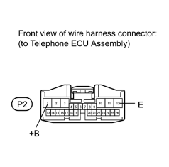
(a) Disconnect the P2 ECU connector. |
(b) Measure the voltage and resistance according to the value(s) in the table below.
Standard Voltage:
Standard Resistance
|
Tester Connection |
Condition |
Specified Condition |
|---|---|---|
|
P2-1 (+B) - Body ground |
Always |
11 to 14 V |
|
Tester Connection |
Condition |
Specified Condition |
|---|---|---|
|
P2-12 (E) - Body ground |
Always |
Below 1 Ω |
|
|
3. |
REPLACE TELEPHONE ECU ASSEMBLY TOGETHER WITH MAYDAY BATTERY |
|

|

|