- Harness or connector
- ID code box (immobiliser code ECU)
- ECM
| Last Modified: 11-27-2007 | 1.6 C | |
| Service Category: Vehicle Interior | Section: Theft Deterrent/Keyless Entry | |
| Model Year: 2008 | Model: LX570 | Doc ID: RM000002UBW008X |
| Title: THEFT DETERRENT / KEYLESS ENTRY: ENGINE IMMOBILISER SYSTEM: DESCRIPTION (2008 LX570) | ||
|
DTC |
B279A |
Theft Deterrent System Communication Line High Fixation |
DESCRIPTION
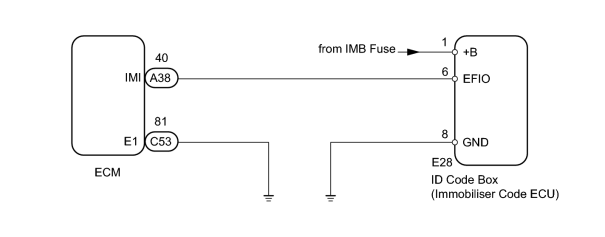
If the communication line (EFIO-IMI) to the ID code box (immobiliser code ECU) is stuck on HI output, the ECM outputs this DTC.
|
DTC Code |
DTC Detection Condition |
Trouble Area |
|---|---|---|
|
B279A |
When the communication line (EFIO-IMI) between the ECM and the ID code box (immobiliser code ECU) is stuck on HI output. |
|
WIRING DIAGRAM
INSPECTION PROCEDURE
PROCEDURE
|
1. |
CLEAR DTC |
(a) Clear the DTCs
 .
.
|

|
2. |
CHECK FOR DTC |
(a) Check for DTCs
.
HINT:
If DTCs other than DTC B279A are output, troubleshoot those DTCs first.
Result
|
Result |
Proceed to |
|---|---|
|
DTC B279A is output |
A |
|
DTC B279A and other DTCs are output |
B |
|
|
3. |
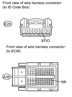
CHECK HARNESS AND CONNECTOR (ID CODE BOX - ECM) |
|
(a) Disconnect the E28 box connector. |
(b) Disconnect the A38 ECM connector.
(c) Measure the resistance and voltage according to the value(s) in the table below.
Standard Resistance:
|
Tester Connection |
Condition |
Specified Condition |
|---|---|---|
|
E28-6 (EFIO) - A38-40 (IMI) |
Always |
Below 1 Ω |
|
E28-6 (EFIO) or A38-40 (IMI) - Body ground |
Always |
10 kΩ or higher |
Standard Voltage:
|
Tester Connection |
Condition |
Specified Condition |
|---|---|---|
|
E28-6 (EFIO) - Body ground |
Always |
Below 1 V |
|
A38-40 (IMI) - Body ground |
|
|
4. |
CHECK ID CODE BOX (IMMOBILISER CODE ECU) (OUTPUT) |
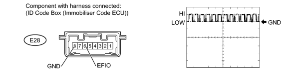
(a) Using an oscilloscope, check the waveform.
Measurement Condition
|
Item |
Content |
|---|---|
|
Terminal No. (Symbol) |
E28-6 (EFIO) - E28-8 (GND) |
|
Tool Setting |
10 V/DIV., 100 msec./DIV. |
|
Condition |
Engine switch on (IG) |
OK:
Waveform is output normally (See illustration).
|
|
5. |
CHECK ID CODE BOX (POWER SOURCE AND BODY GROUND) |
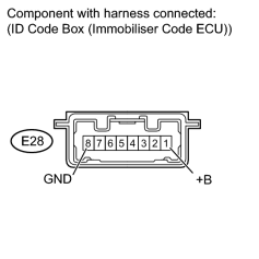
(a) Turn the engine switch on (IG).
(b) Measure the voltage according to the value(s) in the table below.
Standard Voltage:
|
Tester Connector |
Condition |
Specified Condition |
|---|---|---|
|
E28-1 (+B) - E28-8 (GND) |
Always |
11 to 14 V |
|

|

|