| Last Modified: 11-27-2007 | 1.6 J | |
| Service Category: Vehicle Exterior | Section: Lighting (ext) | |
| Model Year: 2008 | Model: LX570 | Doc ID: RM000002WKT006X |
| Title: LIGHTING (EXT): LIGHTING SYSTEM: DESCRIPTION (2008 LX570) | ||
|
LO-beam Headlight does not Illuminate |
DESCRIPTION
The main body ECU receives a headlight switch information signal from the light control switch, and illuminates the headlight low beam.
WIRING DIAGRAM
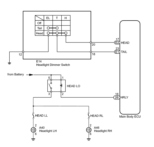
INSPECTION PROCEDURE
PROCEDURE
|
1. |
READ VALUE USING TECHSTREAM (HEADLIGHT DIMMER SWITCH) |
(a) Using the Techstream, read the Data List.
Main Body
|
Tester Display |
Measurement Item/Range |
Normal Condition |
Diagnostic Note |
|---|---|---|---|
|
Head Light SW (Head) |
Headlight dimmer switch (Head) signal/ON or OFF |
ON: Headlight dimmer switch (Head) on OFF: Headlight dimmer switch off |
- |
OK:
When the headlight dimmer switch operation is performed, the result will be the same as above.
|

|
2. |
PERFORM ACTIVE TEST USING TECHSTREAM (HEADLIGHT) |
(a) Using the Techstream, perform the Active Test.
Main Body
|
Tester Display |
Test Part |
Control Range |
Diagnostic Note |
|---|---|---|---|
|
Head Light Relay |
Headlight |
ON or OFF |
- |
OK:
Headlight low beam turns on/off.
|
|
3. |
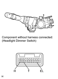
INSPECT HEADLIGHT DIMMER SWITCH |
|
(a) Remove the headlight dimmer switch
|

(b) Measure the resistance according to the value(s) in the table below.
Standard Resistance:
|
Tester Connection |
Switch Condition |
Specified Condition |
|---|---|---|
|
18 (T) - 12 (EL) |
Headlight dimmer switch (Light control switch) head |
Below 1 Ω |
|
18 (T) - 12 (EL) |
Headlight dimmer switch (Light control switch) off |
10 kΩ or higher |
|
|
4. |
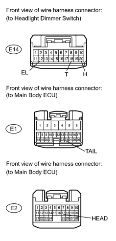
CHECK HARNESS AND CONNECTOR (HEADLIGHT DIMMER SWITCH - MAIN BODY ECU AND BODY GROUND) |
|
(a) Disconnect the E14 switch connector. |
(b) Disconnect the E1 and E2 ECU connectors.
(c) Measure the resistance according to the value(s) in the table below.
Standard Resistance:
|
Tester Connection |
Condition |
Specified Condition |
|---|---|---|
|
E14-20 (H) - E2-17 (HEAD) |
Always |
Below 1 Ω |
|
E14-18 (T) - E1-23 (TAIL) |
||
|
E14-12 (EL) - Body ground |
||
|
E14-20 (H) - Body ground |
Always |
10 kΩ or higher |
|
E14-18 (T) - Body ground |
|
|
5. |
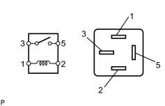
INSPECT HEADLIGHT RELAY (HEAD LO) |
|
(a) Remove the headlight relay from the engine room relay block, junction block. |
(b) Measure the resistance according to the value(s) in the table below.
Standard Resistance:
|
Tester Connection |
Condition |
Specified Condition |
|---|---|---|
|
3 - 5 |
Battery voltage not applied to terminals 1 and 2 |
10 kΩ or higher |
|
Battery voltage applied to terminals 1 and 2 |
Below 1 Ω |
|
|
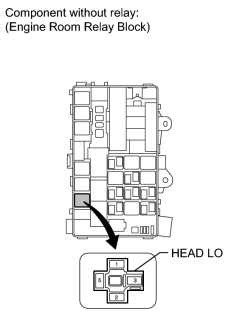
6. |
CHECK HARNESS AND CONNECTOR (HEADLIGHT RELAY (HEAD LO) - BATTERY) |
|
(a) Remove the headlight relay from the engine room relay block. |
(b) Measure the voltage according to the value(s) in the table below.
Standard Voltage:
|
Tester Connection |
Condition |
Specified Condition |
|---|---|---|
|
HEAD LO relay terminal 1 - Body ground |
Always |
11 to 14 V |
|
HEAD LO relay terminal 5 - Body ground |
|
|
7. |
CHECK HARNESS AND CONNECTOR (HEADLIGHT - HEADLIGHT RELAY (HEAD LO) AND BODY GROUND) |
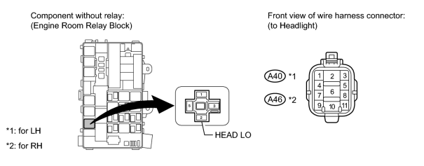
(a) Remove the headlight relay from the engine room relay block.
(b) Disconnect the A40 and A46 light connectors.
(c) Measure the resistance according to the value(s) in the table below.
Standard Resistance:
for LH
for RH
|
Tester Connection |
Condition |
Specified Condition |
|---|---|---|
|
HEAD LO relay terminal 3 - A40-2 |
Always |
Below 1 Ω |
|
A40-6 - Body ground |
||
|
A40-2 - Body ground |
Always |
10 kΩ or higher |
|
Tester Connection |
Condition |
Specified Condition |
|---|---|---|
|
HEAD LO relay terminal 3 - A46-2 |
Always |
Below 1 Ω |
|
A46-6 - Body ground |
||
|
A46-2 - Body ground |
Always |
10 kΩ or higher |
|
|
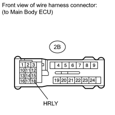
8. |
CHECK HEADLIGHT (LOW BEAM) |
|
(a) Disconnect the 2B ECU connector. |
(b) Using a service wire, connect terminal 2B-18 (HRLY) on the wire harness side and the body ground.
(c) Check that the headlight low beam illuminates.
OK:
Headlight low beam illuminates.
|

|

|