| Last Modified: 11-27-2007 | 1.6 U | |
| Service Category: Vehicle Exterior | Section: Mirror (ext) | |
| Model Year: 2008 | Model: LX570 | Doc ID: RM000002Y3X004X |
| Title: MIRROR (EXT): POWER MIRROR CONTROL SYSTEM: TERMINALS OF ECU (2008 LX570) | ||
TERMINALS OF ECU
1. CHECK OUTER MIRROR CONTROL ECU
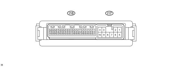
(a) Disconnect the I17 ECU connector.
(b) Measure the voltage and resistance of the wire harness side connector.
|
Terminal No. (Symbol) |
Wiring Color |
Terminal Description |
Condition |
Specified Condition |
|---|---|---|---|---|
|
I17-9 (GND) - Body ground |
W-B - Body ground |
Ground |
Always |
Below 1 Ω |
|
I17-3 (B) - I17-9 (GND) |
R - W-B |
Battery (ECU power source) |
Always |
11 to 14 V |
|
I17-4 (ACC) - I17-9 (GND) |
GR - W-B |
ACC power supply |
Engine switch off |
Below 1 V |
|
Engine switch on (ACC) |
11 to 14 V |
If the result is not as specified, there may be a malfunction on the wire harness side.
(c) Reconnect the I17 ECU connector.
(d) Measure the voltage of the connector.
|
Terminal No. (Symbol) |
Wiring Color |
Terminal Description |
Condition |
Specified Condition |
|---|---|---|---|---|
|
I17-1 (RL) - I17-9 (GND) |
LG - W-B |
Mirror retract motor output (retracting) |
Mirror retract switch on (Outer rear view mirror LH retracting) |
10.3 to 14 V |
|
I17-2 (FL) - I17-9 (GND) |
SB - W-B |
Mirror retract motor output (returning) |
Mirror retract switch off (Outer rear view mirror LH returning) |
10.3 to 14 V |
|
I17-5 (RR) - I17-9 (GND) |
BR - W-B |
Mirror retract motor output (retracting) |
Mirror retract switch on (Outer rear view mirror RH retracting) |
10.3 to 14 V |
|
I17-6 (FR) - I17-9 (GND) |
R - W-B |
Mirror retract motor output (returning) |
Mirror retract switch off (Outer rear view mirror RH returning) |
10.3 to 14 V |
|
I18-18 (M+L) - I17-9 (GND) |
Y - W-B |
Mirror motor output |
Mirror master switch L, Mirror control switch off |
Below 1 V |
|
Mirror master switch L, Mirror control switch up or left |
Below 1 V |
|||
|
Mirror master switch L, Mirror control switch down or right |
10 to 14 V |
|||
|
I18-19 (MHL) - I17-9 (GND) |
G - W-B |
Mirror motor output |
Mirror master switch L, Mirror control switch off |
Below 1 V |
|
Mirror master switch L, Mirror control switch right |
Below 1 V |
|||
|
Mirror master switch L, Mirror control switch left |
10 to 14 V |
|||
|
I18-20 (MVL) - I17-9 (GND) |
L - W-B |
Mirror motor output |
Mirror master switch L, Mirror control switch off |
Below 1 V |
|
Mirror master switch L, Mirror control switch down |
Below 1 V |
|||
|
Mirror master switch L, Mirror control switch up |
10 to 14 V |
|||
|
I18-38 (M+R) - I17-9 (GND) |
Y - W-B |
Mirror motor output |
Mirror master switch R, Mirror control switch off |
Below 1 V |
|
Mirror master switch R, Mirror control switch up or left |
Below 1 V |
|||
|
Mirror master switch R, Mirror control switch down or right |
10 to 14 V |
|||
|
I18-39 (MHR) - I17-9 (GND) |
G - W-B |
Mirror motor output |
Mirror master switch R, Mirror control switch off |
Below 1 V |
|
Mirror master switch R, Mirror control switch right |
Below 1 V |
|||
|
Mirror master switch R, Mirror control switch left |
10 to 14 V |
|||
|
I18-40 (MVR) - I17-9 (GND) |
R - W-B |
Mirror motor output |
Mirror master switch R, Mirror control switch off |
Below 1 V |
|
Mirror master switch R, Mirror control switch down |
Below 1 V |
|||
|
Mirror master switch R, Mirror control switch up |
10 to 14 V |
|||
|
I18-4 (VSR) - I18-3 (LE1) |
GR - BR |
Vertical direction position signal |
Mirror master switch R or L Mirror control switch up or down |
Voltage fluctuates between 0 and 5 V |
|
I18-5 (HSRL) - I18-3 (LE1) |
L - BR |
Horizontal direction position signal |
Mirror master switch R or L Mirror control switch right or left |
Voltage fluctuates between 0 and 5 V |
|
I18-2 (LVC) - I18-3 (LE1) |
B - BR |
Power source for mirror position sensor |
Engine switch off during sleep mode |
Below 1 V |
|
Engine switch on (IG) |
4.7 to 5.5 V |
|||
|
I18-24 (VSRR) - I18-23 (RE1) |
GR - BR |
Vertical direction position signal |
Mirror master switch R or L Mirror control switch up or down |
Voltage fluctuates between 0 and 5 V |
|
I18-25 (HSRR) - I18-23 (RE1) |
W - BR |
Horizontal direction position signal |
Mirror master switch R or L Mirror control switch right or left |
Voltage fluctuates between 0 and 5 V |
|
I18-22 (RVC) - I18-23 (RE1) |
B - BR |
Power source for mirror position sensor |
Engine switch off during sleep mode |
Below 1 V |
|
Engine switch on (IG) |
4.7 to 5.5 V |
If the result is not as specified, the ECU may have a malfunction.
2. CHECK MAIN BODY ECU
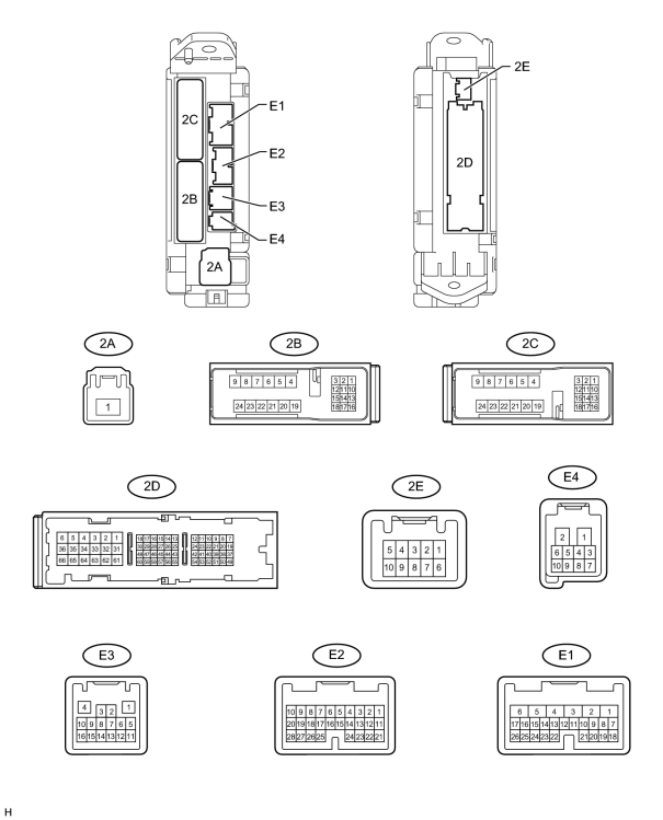
(a) Disconnect the 2B, 2A and 2D ECU connectors.
(b) Measure the voltage and resistance of the wire harness side connectors.
|
Terminal No. (Symbol) |
Wiring Color |
Terminal Description |
Condition |
Specified Condition |
|---|---|---|---|---|
|
2B-20 (BATB) - Body ground |
L - Body ground |
BATB power supply |
Always |
11 to 14 V |
|
2A-1 (ACC) - Body ground |
B - Body ground |
ACC power supply |
Always |
11 to 14 V |
|
2A-1 (IG) - Body ground |
B - Body ground |
IG power supply |
Always |
11 to 14 V |
|
2D-62 (GND2) - Body ground |
W-B - Body ground |
Body ground |
Always |
Below 1 Ω |
If the result is not as specified, there may be a malfunction on the wire harness side.
(c) Reconnect the 2B, 2A and 2D ECU connectors.
(d) Measure the voltage of the connectors.
|
Terminal No. (Symbol) |
Wiring Color |
Terminal Description |
Condition |
Specified Condition |
|---|---|---|---|---|
|
E2-6 (RET) - 2D-62 (GND2) |
BR - W-B |
Mirror retract motor output |
Mirror retract switch in fold position |
11 to 14 V |
|
E2-6 (RET) - 2D-62 (GND2) |
BR - W-B |
Mirror retract motor output |
Mirror retract switch not in fold position |
Below 1 V |
|
E4-8 (AMR) - 2D-62 (GND2) |
V - W-B |
Mirror retract motor output |
Mirror retract switch in AUTO position |
11 to 14 V |
|
E4-8 (AMR) - 2D-62 (GND2) |
V - W-B |
Mirror retract motor output |
Mirror retract switch not in AUTO position |
Below 1 V |
|
E1-12 (MIRS) - E1-2 (MIRE) |
LG - BR |
Mirror motor output |
Mirror master switch L |
11 to 14 V |
|
Mirror master switch R |
11 to 14 V |
|||
|
Mirror master switch off |
Below 1 V |
|||
|
E1-11 (MIRB) - E1-2 (MIRE) |
V - BR |
Mirror motor output |
Mirror master switch L, Mirror control switch right |
11 to 14 V |
|
Mirror master switch L, Mirror control switch left |
11 to 14 V |
|||
|
Mirror master switch L, Mirror control switch down |
11 to 14 V |
|||
|
Mirror master switch L, Mirror control switch up |
11 to 14 V |
|||
|
Mirror master switch R, Mirror control switch right |
11 to 14 V |
|||
|
Mirror master switch R, Mirror control switch left |
11 to 14 V |
|||
|
Mirror master switch R, Mirror control switch down |
11 to 14 V |
|||
|
Mirror master switch R, Mirror control switch up |
11 to 14 V |
|||
|
Mirror master switch off |
Below 1 V |
If the result is not as specified, the ECU may have a malfunction.

|

|