| Last Modified: 11-27-2007 | 1.6 J | |
| Service Category: Vehicle Exterior | Section: Mirror (ext) | |
| Model Year: 2008 | Model: LX570 | Doc ID: RM000002Y45004X |
| Title: MIRROR (EXT): POWER MIRROR CONTROL SYSTEM: SYSTEM DESCRIPTION (2008 LX570) | ||
|
Front Passenger Side Power Mirror cannot be Adjusted with Power Mirror Switch |
SYSTEM DESCRIPTION
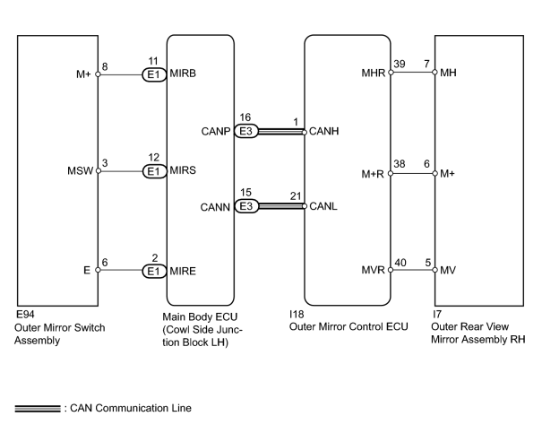
The circuit detects the conditions of the outer mirror switch.
The outer mirror switch sends information about the operating condition of the mirror switch (switch input signals) through the CAN communication line. Then the switch input signals are sent to the outer mirror control ECU. Mirror adjustment is controlled by the outer mirror control ECU.
WIRING DIAGRAM
INSPECTION PROCEDURE
PROCEDURE
|
1. |
CHECK DTC |
(a) Use the Techstream to check if the CAN communication system is functioning normally
 .
.
Result
|
Result |
Proceed to |
|---|---|
|
CAN DTC is not output |
A |
|
CAN DTC is output |
B |
|

|
2. |
READ VALUE USING TECHSTREAM (OUTER MIRROR SWITCH) |
(a) Check the Data List for proper functioning of the outer mirror switch
.
Main Body
|
Tester Display |
Measurement Item/Range |
Normal Condition |
Diagnostic Note |
|---|---|---|---|
|
Mirror Selection SW (R) |
Mirror master switch signal for RH mirror / ON or OFF |
ON: Switch in R position OFF: Switch off or in L position |
- |
|
Mirror Position SW (R) |
Mirror control switch signal (right) / ON or OFF |
ON: Right switch on OFF: Any switch except right on or all switches off |
- |
|
Mirror Position SW (L) |
Mirror control switch signal (left) / ON or OFF |
ON: Left switch on OFF: Any switch except left on or all switches off |
- |
|
Mirror Position SW (Up) |
Mirror control switch signal (up) / ON or OFF |
ON: Up switch on OFF: Any switch except up on or all switches off |
- |
|
Mirror Position SW (Dwn) |
Mirror control switch signal (down) / ON or OFF |
ON: Down switch on OFF: Any switch except down on or all switches off |
- |
OK:
On the Techstream screen, each item changes between ON and OFF according to above chart.
|
|
3. |
PERFORM ACTIVE TEST USING TECHSTREAM (POWER MIRROR CONTROL FUNCTION) |
(a) Select the Active Test, use the Techstream to generate a control command, and then check the power mirror control function
.
Mirror
|
Tester Display |
Test Part |
Control Range |
Diagnostic Note |
|---|---|---|---|
|
RH Mirror Up/Down |
Mirror vertical operation |
Up / OFF / Down |
- |
|
RH Mirror Right/Left |
Mirror horizontal operation |
Right / OFF / Left |
- |
Result
|
Result |
Proceed to |
|---|---|
|
Outer rear view mirror RH does not operate normally |
A |
|
Outer rear view mirror RH operates normally |
B |
|
|
4. |
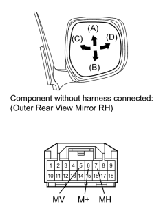
INSPECT OUTER REAR VIEW MIRROR ASSEMBLY RH |
|
(a) Remove the mirror RH
|
(b) Apply battery voltage and check the operation of the power mirror.
OK:
|
Measurement Condition |
Specified Condition |
|---|---|
|
Battery positive (+) → Terminal 5 (MV) Battery negative (-) → Terminal 6 (M+) |
Turns upward (A) |
|
Battery negative (-) → Terminal 5 (MV) Battery positive (+) → Terminal 6 (M+) |
Turns downward (B) |
|
Battery positive (+) → Terminal 7 (MH) Battery negative (-) → Terminal 6 (M+) |
Turns left (C) |
|
Battery negative (-) → Terminal 7 (MH) Battery positive (+) → Terminal 6 (M+) |
Turns right (D) |
|
|
5. |
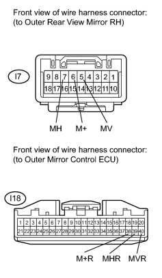
CHECK HARNESS AND CONNECTOR (OUTER REAR VIEW MIRROR RH - OUTER MIRROR CONTROL ECU) |
|
(a) Disconnect the I18 ECU connector. |
(b) Disconnect the I7 mirror connector.
(c) Measure the resistance according to the value(s) in the table below.
Standard Resistance:
|
Tester Connection |
Condition |
Specified Condition |
|---|---|---|
|
I18-38 (M+R) - I7-6 (M+) |
Always |
Below 1 Ω |
|
I18-39 (MHR) - I7-7 (MH) |
||
|
I18-40 (MVR) - I7-5 (MV) |
||
|
I7-6 (M+) - Body ground |
Always |
10 kΩ or higher |
|
I7-7 (MH) - Body ground |
||
|
I7-5 (MV) - Body ground |
|
|
6. |
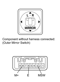
INSPECT OUTER MIRROR SWITCH ASSEMBLY |
|
(a) Remove the outer mirror switch
|
(b) Measure the resistance according to the value(s) in the table below.
Standard Resistance:
|
Tester Connection |
Switch Condition |
Specified Condition |
|---|---|---|
|
8 (M+) - 6 (E) |
Up switch pushed |
90 to 110 Ω |
|
Down switch pushed |
437 to 502 Ω |
|
|
Left switch pushed |
744 to 856 Ω |
|
|
Right switch pushed |
207 to 253 Ω |
|
|
No switches pushed |
10 kΩ or higher |
|
|
3 (MSW) - 6 (E) |
Mirror master switch R |
Below 1 Ω |
|
Mirror master switch off |
10 kΩ or higher |
|
|
7. |
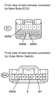
CHECK HARNESS AND CONNECTOR (OUTER MIRROR SWITCH - MAIN BODY ECU) |
|
(a) Disconnect the E1 ECU connector. |
(b) Disconnect the E94 switch connector.
(c) Measure the resistance according to the value(s) in the table below.
Standard Resistance:
|
Tester Connection |
Condition |
Specified Condition |
|---|---|---|
|
E1-2 (MIRE) - E94-6 (E) |
Always |
Below 1 Ω |
|
E1-11 (MIRB) -E94-8 (M+) |
||
|
E1-12 (MIRS) - E94-3 (MSW) |
||
|
E94-6 (E) - Body ground |
Always |
10 kΩ or higher |
|
E94-8 (M+) - Body ground |
||
|
E94-3 (MSW) - Body ground |
|

|

|