| Last Modified: 11-27-2007 | 1.6 U | |
| Service Category: Vehicle Exterior | Section: Window/Glass | |
| Model Year: 2008 | Model: LX570 | Doc ID: RM000002ZC900BX |
| Title: WINDOW / GLASS: WINDSHIELD DEICER SYSTEM: TERMINALS OF ECU (2008 LX570) | ||
TERMINALS OF ECU
1. CHECK AIR CONDITIONING AMPLIFIER
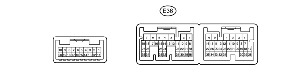
(a) Disconnect the E36 air conditioning amplifier connector.
(b) Measure the resistance and voltage according to the value(s) in the table below.
|
Terminal No. (Symbol) |
Wiring Color |
Terminal Description |
Condition |
Specified Condition |
|---|---|---|---|---|
|
E36-5 (IG+) - E36-1 (GND) |
G - W-B |
Ignition power supply |
Engine switch on (IG) |
11 to 14 V |
|
Engine switch off |
Below 1 V |
|||
|
E36-6 (+B1) - E36-1 (GND) |
R - W-B |
Battery power source |
Always |
11 to 14 V |
|
E36-7 (+B2) - E36-1 (GND) |
R - W-B |
Battery power source |
Always |
11 to 14 V |
|
E36-1 (GND) - Body ground |
W-B - Body ground |
Ground |
Always |
Below 1 Ω |
If the result is not as specified, there may be a malfunction on the wire harness side.
(c) Reconnect the E36 air conditioning amplifier connector.
(d) Measure the voltage according to the value(s) in the table below.
|
Terminal No. (Symbol) |
Wiring Color |
Terminal Description |
Condition |
Specified Condition |
|---|---|---|---|---|
|
E36-23 (FDEF) - E36-1 (GND) |
GR - W-B |
Deicer relay |
Engine switch on (IG) and deicer switch off |
11 to 14 V |
|
Engine switch on (IG) and deicer switch on |
Below 1 V |
If the result is not as specified, the air conditioning amplifier or fuse may have a malfunction.
2. CHECK DISPLAY AND NAVIGATION MODULE DISPLAY (w/ Navigation System)

(a) Disconnect the F28 display and navigation module display connector.
(b) Measure the resistance and voltage according to the value(s) in the table below.
|
Terminal No. (Symbol) |
Wiring Color |
Terminal Description |
Condition |
Specified Condition |
|---|---|---|---|---|
|
F28-3 (IG) - F28-10 (GND1) |
G - W-B |
Ignition power supply |
Engine switch on (IG) |
11 to 14 V |
|
Engine switch off |
Below 1 V |
|||
|
F28-1 (B+) - F28-10 (GND1) |
R - W-B |
Battery power source |
Always |
11 to 14 V |
|
F28-10 (GND1) - Body ground |
W-B - Body ground |
Ground |
Always |
Below 1 Ω |
If the result is not as specified, there may be a malfunction on the wire harness side.
3. CHECK MULTI-DISPLAY (w/o Navigation System)
(a) Disconnect the F28 multi-display connector.
(b) Measure the resistance and voltage according to the value(s) in the table below.
|
Terminal No. (Symbol) |
Wiring Color |
Terminal Description |
Condition |
Specified Condition |
|---|---|---|---|---|
|
F28-3 (IG) - F28-10 (GND1) |
G - W-B |
Ignition power supply |
Engine switch on (IG) |
11 to 14 V |
|
Engine switch off |
Below 1 V |
|||
|
F28-1 (B+) - F28-10 (GND1) |
R - W-B |
Battery power source |
Always |
11 to 14 V |
|
F28-10 (GND1) - Body ground |
W-B - Body ground |
Ground |
Always |
Below 1 Ω |
If the result is not as specified, there may be a malfunction on the wire harness side.

|

|