| Last Modified: 11-27-2007 | 1.6 G | |
| Service Category: Vehicle Exterior | Section: Horn | |
| Model Year: 2008 | Model: LX570 | Doc ID: RM0000030EL006X |
| Title: HORN: HORN RELAY: ON-VEHICLE INSPECTION (2008 LX570) | ||
ON-VEHICLE INSPECTION
1. REMOVE ENGINE ROOM SIDE COVER LH

2. DISCONNECT CABLE FROM NEGATIVE BATTERY TERMINAL
CAUTION:
Wait at least 90 seconds after disconnecting the cable from the negative (-) battery terminal to disable the SRS system.
NOTICE:
-
w/ Navigation System:
After the engine switch is turned off, the HDD navigation system requires approximately 6 minutes to record various types of memory and settings. As a result, after turning the engine switch off, wait 6 minutes or more before disconnecting the cable from the negative (-) battery terminal.
-
When disconnecting the cable, some systems need to be initialized after the cable is reconnected
.
3. REMOVE INTEGRATION RELAY (UNIT C)
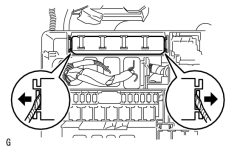
(a) Remove the engine room relay block cover.
|
(b) Using a screwdriver, detach the 2 claws and remove the integration relay from the engine room relay block. HINT:
Tape the screwdriver tip before use. |
(c) Disconnect the 3 connectors.
4. INSPECT INTEGRATION RELAY (HORN RELAY)
NOTICE:
- Some relays are built into the integration relay (unit C). The integration relay cannot be disassembled. If there is a malfunction in the circuit of the integration relay, replace the integration relay.
- The internal circuit of the integration relay is as shown in the illustration below. Inspect the integration relay using the following procedures.
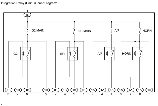
(a) Measure the resistance of the HORN fuse.
(1) Measure the resistance according to the value(s) in the table below.
Standard Resistance:
|
Tester Connection |
Condition |
Specified Condition |
|---|---|---|
|
HORN fuse |
Always |
Below 1 Ω |
If the result is not as specified, replace the HORN fuse.
|
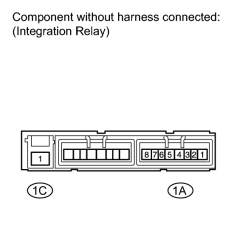
(b) Measure the resistance of the horn relay circuit. (1) Measure the resistance according to the value(s) in the table below. Standard Resistance:
If the result is not as specified, replace the integration relay. |
5. INSTALL INTEGRATION RELAY (UNIT C)
(a) Connect the 3 connectors.
(b) Attach the 2 claws to install the integration relay to the engine room relay block.
(c) Install the engine room relay block cover.
6. CONNECT CABLE TO NEGATIVE BATTERY TERMINAL
NOTICE:
When disconnecting the cable, some systems need to be initialized after the cable is reconnected
.
7. INSTALL ENGINE ROOM SIDE COVER LH

|

|