| Last Modified: 11-27-2007 | 1.6 D | |
| Service Category: Audio/Visual/Telematics | Section: Park Assist/Monitoring | |
| Model Year: 2008 | Model: LX570 | Doc ID: RM0000035BA002X |
| Title: PARK ASSIST / MONITORING: INTUITIVE PARKING ASSIST SYSTEM: OPERATION CHECK (2008 LX570) | ||
OPERATION CHECK
HINT:
If the vehicle has a navigation system, "multi-display" refers to the "display and navigation module display".
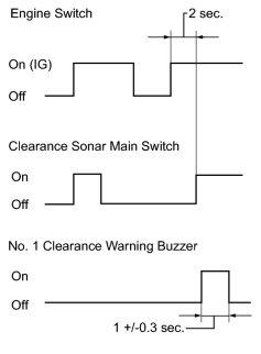
1. INITIAL CHECK FUNCTION
(a) Turn the engine switch on (IG).
(b) After 2 seconds or more have passed, turn the clearance sonar main switch on. Then check the buzzer sounding condition.
Buzzer sounding:
1 +/-0.3 seconds
HINT:
- If a malfunction is detected in the ultrasonic sensor circuits, the location of the malfunctioning sensor blinks on the displayed vehicle graphic. However, after the sensor returns to normal, the display also returns to normal.
- When the engine switch is turned on (IG) while the clearance sonar main switch is on, the buzzer will not sound.
2. MALFUNCTION OF MULTI-INFORMATION DISPLAY
(a) Ultrasonic sensor open circuit
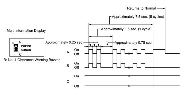
(1) If there is an open circuit between the ultrasonic sensor and the ECU or a sensor is malfunctioning, the malfunction is displayed as shown in the illustration.
HINT:
- The example shows an open circuit in the No. 1 ultrasonic sensor (front left sensor).
- If a sensor has an open circuit, "CHECK SONAR" is displayed. Refer to "Open circuit in front sensor is displayed as a result of self-check" in the problem symptoms table to inspect it.
(b) Ultrasonic sensor frozen
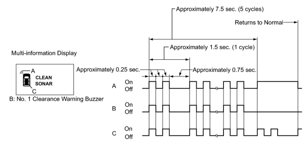
(1) If a sensor is covered with foreign matter, such as mud or snow, the affected sensor is displayed as shown in the illustration.
HINT:
- The example shows that the No. 1 ultrasonic sensor (front left sensor) is covered with foreign matter.
- If "CLEAN SONAR" is displayed, cleaning the foreign matter from the sensor will return the sensor to normal.
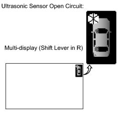
3. MALFUNCTION OF MULTI-DISPLAY
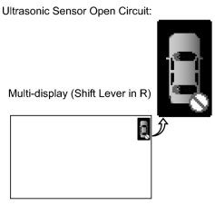
(a) Ultrasonic sensor open circuit
|
(1) If there is an open circuit between the ultrasonic sensor and the ECU or a sensor is malfunctioning, the malfunction is displayed as shown in the illustration. HINT:
This example shows an open circuit in the No. 2 ultrasonic sensor (rear right sensor). |
(b) Ultrasonic sensor frozen
|
(1) If a sensor is covered with foreign matter, such as mud or snow, the affected sensor is displayed as shown in the illustration. HINT:
The example shows that the No. 1 ultrasonic sensor (front left sensor) is covered with foreign matter. |
4. DETECTION RANGE MEASUREMENT AND DISPLAY CHECK
NOTICE:
Apply the parking brake securely so that the vehicle does not move.
(a) Turn the engine switch on (IG).
(b) Turn the clearance sonar main switch on.
(c) Move the shift lever to R to check the No. 1 ultrasonic sensors, No. 2 ultrasonic sensors and No. 3 ultrasonic sensors.
(d) Move the shift lever to D and N to check the No. 1 ultrasonic sensors.
(e) Move a φ60 mm (2.36 in.) pole around the sensor to measure the detection range of the sensor.
NOTICE:
- These detection ranges are applicable when positioning the φ60 mm (2.36 in.) pole parallel or perpendicular to the ground.
- The ranges vary depending on the measuring method and type of obstacle (such as walls).
- For close-range and medium-range detection, the values shown are for when using a pole with a diameter of 60 mm (2.36 in.). For long-range detection, the values shown are for when using walls.
- The detection range of the resin bumper and steel bumper are not the same, as their installation positions are slightly different.
(1) No. 1 ultrasonic sensors detection range
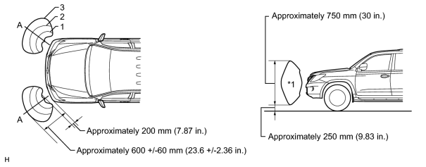
NOTICE:
The area (labeled *1) which represents a side view of the No. 1 ultrasonic sensor detection range is a cross section of the detection range at the position labeled A which is shown in the top view. The area (labeled *1) does not represent the entire detection range.
(2) No. 2 ultrasonic sensor detection range
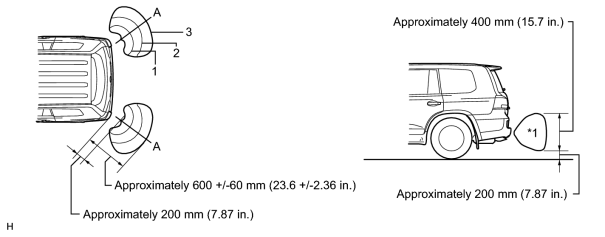
NOTICE:
The area (labeled *1) which represents a side view of the No. 2 ultrasonic sensor detection range is a cross section of the detection range at the position labeled A which is shown in the top view. The area (labeled *1) does not represent the entire detection range.
(3) No. 3 ultrasonic sensor detection range
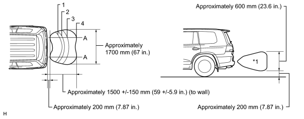
NOTICE:
The area (labeled *1) which represents a side view of the No. 3ultrasonic sensor detection range is a cross section of the detection range at the position labeled A which is shown in the top view. The area (labeled *1) does not represent the entire detection range.
(f) When the ultrasonic sensors have detected an obstacle, check the multi-display, multi-information display and that the No. 1 clearance warning buzzer sounds with the clearance sonar main switch on.
Operation Condition
|
Shift Lever Position |
Vehicle Speed |
Multi-display Detection, Multi-information Display Detection, Buzzer Detection |
||
|---|---|---|---|---|
|
No. 1 Ultrasonic Sensor |
No. 2 Ultrasonic Sensor |
No. 3 Ultrasonic Sensor |
||
|
P |
- |
Only perform check operation |
||
|
D, S, (N) |
9 km/h (5.6 mph) or less |
○ |
X |
X |
|
R |
No limit |
○ |
○ |
○ |
(1) Check that the buzzer sounds with the clearance sonar main switch on as shown in the illustration.
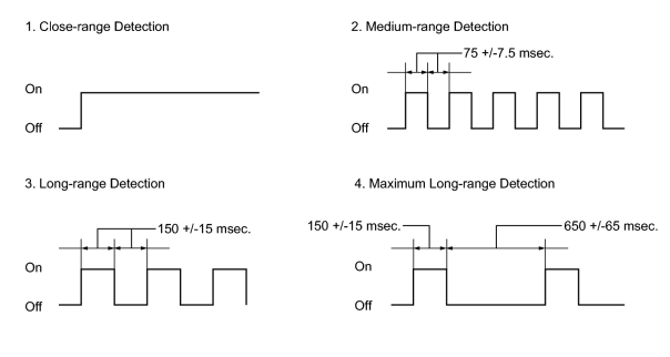
No. 1 Ultrasonic Sensor Detection Range
|
Detection |
Distance |
|---|---|
|
1. Close-range detection |
Within 350 +/-40 mm (13.8 +/-1.57 in.) |
|
2. Medium-range detection |
350 +/-40 to 475 +/-50 mm (13.8 +/-1.57 to 18.7 +/-1.96 in.) |
|
3. Long-range detection |
475 +/-50 to 600 +/-60 mm (18.7 +/-1.96 to 23.6 +/-2.36 in.) |
No. 2 Ultrasonic Sensor Detection Range
|
Detection |
Distance |
|---|---|
|
1. Close-range detection |
Within 300 +/-30 mm (11.8 +/-1.18 in.) |
|
2. Medium-range detection |
300 +/-30 to 375 +/-40 mm (11.8 +/-1.18 to 14.8 +/-1.57 in.) |
|
3. Long-range detection |
375 +/-40 to 600 +/-60 mm (14.8 +/-1.57 to 23.6 +/-2.36 in.) |
No. 3 Ultrasonic Sensor Detection Range
|
Detection |
Distance |
|---|---|
|
1. Close-range detection |
Within 350 +/-40 mm (13.8 +/-1.57 in.) |
|
2. Medium-range detection |
350 +/-40 to 450 +/-50 mm (13.8 +/-1.57 to 17.7 +/-1.96 in.) |
|
3. Long-range detection |
450 +/-50 to 600 +/-60 mm (17.7 +/-1.96 to 23.6 +/-2.36 in.) |
|
4. Maximum long-range detection |
600 +/-60 to 1500 +/-150 mm (23.6 +/-2.36 to 59.1 +/-5.91 in.) |
HINT:
Ultrasonic waves are used to measure the detection range. However, the detection range may vary depending on the ambient temperature.
(2) Check the multi-information display and buzzer when the No. 1 ultrasonic sensors have detected an obstacle.
Operation Condition
|
Engine Switch |
Clearance Sonar Main Switch |
Shift Lever Position |
Vehicle Speed |
|---|---|---|---|
|
On (IG) |
On |
D or N |
9 km/h (5.6 mph) or less |

Multi-information Display
|
Detection Range |
Buzzer |
Number of Bars Displayed |
|---|---|---|
|
1. Close-range detection |
Sounds continuously |
1 (blinking) |
|
2. Medium-range detection |
Sounds intermittently (On: 75 msec., Off: 75 msec.) |
2 (illuminated) |
|
3. Long-range detection |
Sounds intermittently (On: 150 msec., Off: 150 msec.) |
3 (illuminated) |

Multi-display
|
Detection Range |
Buzzer |
Number of Bars Displayed |
|---|---|---|
|
1. Close-range detection |
Sounds continuously |
1 (red illumination) |
|
2. Medium-range detection |
Sounds intermittently (On: 75 msec., Off: 75 msec.) |
2 (yellow illumination) |
|
3. Long-range detection |
Sounds intermittently (On: 150 msec., Off: 150 msec.) |
3 (yellow illumination) |
HINT:
Ultrasonic waves are used to measure the detection range. However, the detection range may vary depending on the ambient temperature.
(3) Check the multi-information display and buzzer when the No. 2 ultrasonic sensors and No. 3 ultrasonic sensors have detected an obstacle.
Operation Condition
|
Engine Switch |
Clearance Sonar Main Switch |
Shift Lever Position |
|---|---|---|
|
On (IG) |
On |
R |

Multi-information Display
|
Detection Range |
Buzzer |
Number of Bars Displayed |
|---|---|---|
|
1. Close-range detection |
Sounds continuously |
1 (blinking) |
|
2. Medium-range detection |
Sounds intermittently (On: 75 msec., Off: 75 msec.) |
2 (illuminated) |
|
3. Long-range detection |
Sounds intermittently (On: 150 msec., Off: 150 msec.) |
3 (illuminated) |
|
4. Maximum long-range detection (for rear center sensors) |
Sounds intermittently (On: 150 msec., Off: 650 msec.) |
4 (illuminated) |
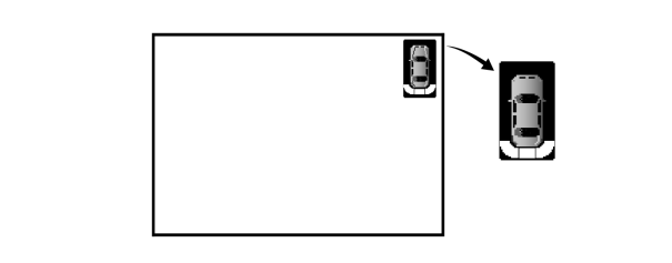
Multi-display
|
Detection Range |
Buzzer |
Number of Bars Displayed |
|---|---|---|
|
1. Close-range detection |
Sounds continuously |
1 (red illumination) |
|
2. Medium-range detection |
Sounds intermittently (On: 75 msec., Off: 75 msec.) |
2 (yellow illumination) |
|
3. Long-range detection |
Sounds intermittently (On: 150 msec., Off: 150 msec.) |
3 (yellow illumination) |
|
4. Maximum long-range detection (for rear center sensors) |
Sounds intermittently (On: 150 msec., Off: 650 msec.) |
4 (yellow illumination) |
HINT:
Ultrasonic waves are used to measure the detection range. However, the detection range may vary depending on the ambient temperature.

|

|