| Last Modified: 11-27-2007 | 1.6 J | |
| Service Category: Audio/Visual/Telematics | Section: Park Assist/Monitoring | |
| Model Year: 2008 | Model: LX570 | Doc ID: RM0000037I7003X |
| Title: PARK ASSIST / MONITORING: REAR VIEW MONITOR SYSTEM: DESCRIPTION (2008 LX570) | ||
|
Display Signal Circuit between Multi-display and Television Camera Assembly |
DESCRIPTION
This is the display signal circuit of the rear television camera.
This inspection procedure is for vehicles that are not equipped with a navigation system.
WIRING DIAGRAM
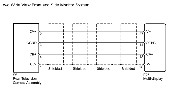
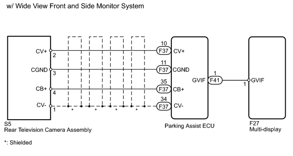
INSPECTION PROCEDURE
PROCEDURE
|
1. |
CHECK REAR TELEVISION CAMERA ASSEMBLY |
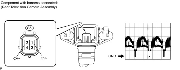
(a) Using an oscilloscope, check the waveform.
Measurement Condition
|
Item |
Content |
|---|---|
|
Terminal No. (Symbol) |
S5-2 (CV+) - S5-1 (CV-) |
|
Tool Setting |
0.2 V/DIV., 20 μs/DIV. |
|
Condition |
Engine switch on (IG), shift lever in R |
OK:
Waveform is as shown in illustration.
|

|
2. |
CHECK VEHICLE TYPE |
(a) Check vehicle type.
Result
|
Result |
Proceed to |
|---|---|
|
w/ Wide View Front and Side Monitor System |
A |
|
w/o Wide View Front and Side Monitor System |
B |
|
|
3. |
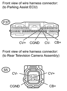
CHECK HARNESS AND CONNECTOR (PARKING ASSIST ECU - REAR TELEVISION CAMERA) |
|
(a) Disconnect the F37 ECU connector. |
(b) Disconnect the S5 camera connector.
(c) Measure the resistance according to the value(s) in the table below.
Standard Resistance:
|
Tester Connection |
Condition |
Specified Condition |
|---|---|---|
|
F37-35 (CB+) - S5-4 (CB+) |
Always |
Below 1 Ω |
|
F37-11 (CGND) - S5-3 (CGND) |
Always |
Below 1 Ω |
|
F37-10 (CV+) - S5-2 (CV+) |
Always |
Below 1 Ω |
|
F37-34 (CV-) - S5-1 (CV-) |
Always |
Below 1 Ω |
|
F37-35 (CB+) - Body ground |
Always |
10 kΩ or higher |
|
F37-11 (CGND) - Body ground |
Always |
10 kΩ or higher |
|
F37-10 (CV+) - Body ground |
Always |
10 kΩ or higher |
|
F37-34 (CV-) - Body ground |
Always |
10 kΩ or higher |
|
|
4. |
REPLACE HARNESS AND CONNECTOR (PARKING ASSIST ECU - MULTI-DISPLAY) |
(a) Replace the digital cable between the parking assist ECU and multi-display with a new one.
|
|
5. |
CHECK REAR VIEW MONITOR SYSTEM |
(a) Turn the engine switch on (IG).
(b) When the shift lever is moved to R, check that the image displays normally on the screen.
OK:
Image displays normally on the screen.
|
|
6. |
CHECK MULTI-DISPLAY |
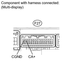
(a) Measure the voltage according to the value(s) in the table below.
Standard Voltage:
|
Tester Connection |
Condition |
Specified Condition |
|---|---|---|
|
F27-13 (CA+) - F27-14 (CGND) |
Engine switch on (IG), shift lever in R |
5.8 to 6.5 V |
|
|
7. |
CHECK DIGITAL CABLE (MULTI-DISPLAY - REAR TELEVISION CAMERA) |
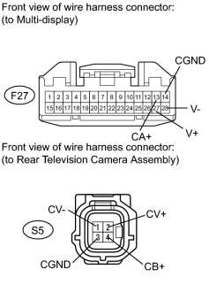
(a) Disconnect the F27 multi-display connector.
(b) Disconnect the S5 camera connector.
(c) Measure the resistance according to the value(s) in the table below.
Standard Resistance:
|
Tester Connection |
Condition |
Specified Condition |
|---|---|---|
|
F27-13 (CA+) - S5-4 (CB+) |
Always |
Below 1 Ω |
|
F27-14 (CGND) - S5-3 (CGND) |
Always |
Below 1 Ω |
|
F27-27 (V+) - S5-2 (CV+) |
Always |
Below 1 Ω |
|
F27-28 (V-) - S5-1 (CV-) |
Always |
Below 1 Ω |
|
F27-13 (CA+) - Body ground |
Always |
10 kΩ or higher |
|
F27-14 (CGND) - Body ground |
Always |
10 kΩ or higher |
|
F27-27 (V+) - Body ground |
Always |
10 kΩ or higher |
|
F27-28 (V-) - Body ground |
Always |
10 kΩ or higher |
|

|

|