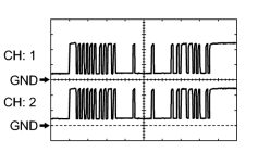
- F37-33 (SOF) - F37-32 (E1)
- F37-30 (SOR) - F37-29 (E2)
| Last Modified: 11-27-2007 | 1.6 U | |
| Service Category: Audio/Visual/Telematics | Section: Park Assist/Monitoring | |
| Model Year: 2008 | Model: LX570 | Doc ID: RM0000037KL002X |
| Title: PARK ASSIST / MONITORING: INTUITIVE PARKING ASSIST SYSTEM: TERMINALS OF ECU (2008 LX570) | ||
TERMINALS OF ECU
1. CHECK PARKING ASSIST ECU
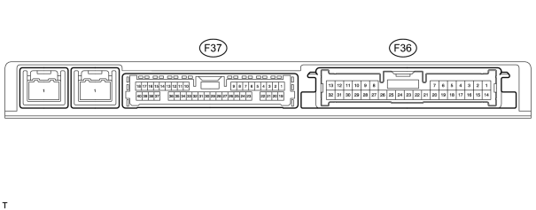
(a) Disconnect the F36 and F37 ECU connectors.
(b) Measure the voltage and resistance according to the value(s) in the table below.
|
Terminal No. (Symbol) |
Wiring Color |
Terminal Description |
Condition |
Specified Condition |
|---|---|---|---|---|
|
F36-6 (+B) - F36-4 (GND1) |
L - W-B |
Power source signal |
Always |
11 to 14 V |
|
F36-1 (IG) - F36-4 (GND1) |
G - W-B |
IG power source signal |
Engine switch on (IG) |
11 to 14 V |
|
F36-1 (IG) - F36-4 (GND1) |
G - W-B |
IG power source signal |
Engine switch off |
Below 1 V |
|
F36-14 (ACC) - F36-4 (GND1) |
GR - W-B |
ACC power source signal |
Engine switch on (ACC) |
11 to 14 V |
|
F36-14 (ACC) - F36-4 (GND1) |
GR - W-B |
ACC power source signal |
Engine switch off |
Below 1 V |
|
F37-6 (CSSW) - F36-4 (GND1) |
Y - W-B |
Clearance sonar main switch power source signal |
Engine switch on (IG), clearance sonar main switch on |
11 to 14 V |
|
F37-6 (CSSW) - F36-4 (GND1) |
Y - W-B |
Clearance sonar main switch power source signal |
Engine switch on (IG), clearance sonar main switch off |
Below 1 V |
|
F36-4 (GND1) - Body ground |
W-B - Body ground |
ECU ground |
Always |
Below 1 Ω |
(c) Reconnect the F36 and F37 ECU connectors.
(d) Measure the voltage according to the value(s) in the table below.
|
Terminal No. (Symbol) |
Wiring Color |
Terminal Description |
Condition |
Specified Condition |
|---|---|---|---|---|
|
F37-28 (BOR) - F37-29 (E2) |
R - GR |
Rear sensor circuit power source |
Engine switch on (IG), clearance sonar main switch on |
7.2 to 8.8 V |
|
F37-28 (BOR) - F37-29 (E2) |
R - GR |
Rear sensor circuit power source |
Engine switch off |
Below 1 V |
|
F37-33 (SOF) - F37-32 (E1) |
LG - R |
Front sensor circuit power source |
Engine switch on (IG), clearance sonar main switch on |
Waveform 1 |
|
F37-25 (BBZ) - F36-4 (GND1) |
G - W-B |
No. 1 clearance warning buzzer signal |
Engine switch on (IG) |
7.2 to 8.8 V |
|
F37-25 (BBZ) - F36-4 (GND1) |
G - W-B |
No. 1 clearance warning buzzer signal |
Engine switch off |
Below 1 V |
|
F37-9 (EF) - F36-4 (GND1) |
L - W-B |
No. 1 clearance warning buzzer signal |
Buzzer sounding |
Waveform 2 |
|
F37-31 (BOF) - F37-32 (E1) |
GR - R |
Front sensor circuit power source |
Engine switch off |
Below 1 V |
|
F37-31 (BOF) - F37-32 (E1) |
GR - R |
Front sensor circuit power source |
Engine switch on (IG), clearance sonar main switch on |
7.2 to 8.8 V |
|
F37-30 (SOR) - F37-29 (E2) |
LG - GR |
Rear sensor circuit power source |
Engine switch on (IG), clearance sonar main switch on |
Waveform 1 |
|
(e) Using an oscilloscope, check waveform 1.
|
|
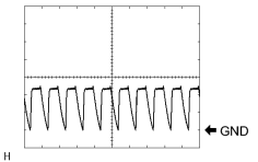
(f) Using an oscilloscope, check waveform 2.
|

|

|