- The center airbag sensor receives an open signal or short to ground in the RSCA OFF indicator circuit.
- An RSCA OFF indicator malfunction.
- A center airbag sensor malfunction.
| Last Modified: 11-27-2007 | 1.6 C | |
| Service Category: Vehicle Interior | Section: Supplemental Restraint Systems | |
| Model Year: 2008 | Model: LX570 | Doc ID: RM0000038B5003X |
| Title: SUPPLEMENTAL RESTRAINT SYSTEMS: AIRBAG SYSTEM: DESCRIPTION (2008 LX570) | ||
|
DTC |
B1661/44 |
Roll Over Cut Off Indicator Malfunction |
DESCRIPTION
The curtain shield airbag cutoff switch is a mechanism that operates both the right and left sides of the curtain shield airbag and the front seat outer belt when the center airbag sensor detects a roll-over.
The RSCA OFF indicator is installed in the combination meter.
If the curtain shield airbag cutoff switch is operated, the indicator comes on to inform the drive that the roll-over detection system is not working.
The initial setting of the roll-over detection system is on. It automatically operates every time the engine switch is turned on (IG).
|
DTC Code |
DTC Detection Condition |
Trouble Area |
|---|---|---|
|
B1661/44 |
When one of the following conditions is met: |
|
WIRING DIAGRAM
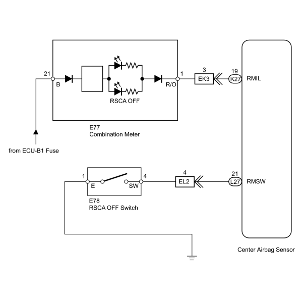
INSPECTION PROCEDURE
NOTICE:
-
w/ Navigation system:
After the engine switch is turned off, the HDD navigation system requires approximately 6 minutes to record various types of memory and settings. As a result, after turning the engine switch off, wait 6 minutes or more before disconnecting the cable from the negative (-) battery terminal.
-
When disconnecting the cable from the negative (-) battery terminal while performing repairs, some systems need to be initialized after the cable is reconnected
 .
.
PROCEDURE
|
1. |
CHECK COMBINATION METER (SOURCE VOLTAGE) |
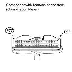
(a) Turn the engine switch off.
(b) Disconnect the cable from the negative (-) battery terminal, and wait for at least 90 seconds.
(c) Remove the combination meter with the connector connected.
(d) Disconnect the connector from the center airbag sensor.
(e) Connect the cable to the negative (-) battery terminal, and wait for at least 2 seconds.
(f) Measure the voltage according to the value(s) in the table below.
Standard Voltage:
|
Tester Connection |
Switch Condition |
Specified Condition |
|---|---|---|
|
E77-1 (R/O) - Body ground |
Engine switch on (IG) |
11 to 14 V |
|

|
2. |
CHECK RSCA OFF INDICATOR CIRCUIT |
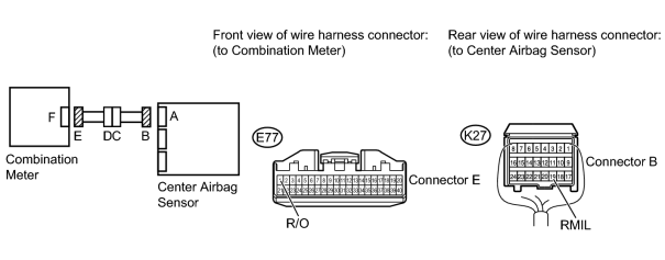
(a) Turn the engine switch off.
(b) Disconnect the cable from the negative (-) battery terminal, and wait for at least 90 seconds.
(c) Disconnect the connector from the center airbag sensor and combination meter.
(d) Measure the resistance according to the value(s) in the table below.
Standard Resistance:
|
Tester Connection |
Condition |
Specified Condition |
|---|---|---|
|
E77-1 (R/O) - K27-19 (RMIL) |
Always |
Below 1 Ω |
|
E77-1 (R/O) - Body ground |
Always |
1 MΩ or higher |
(e) Connect the cable to the negative (-) battery terminal, and wait for at least 2 seconds.
(f) Measure the voltage according to the value(s) in the table below.
Standard Voltage:
|
Tester Connection |
Switch Condition |
Specified Condition |
|---|---|---|
|
E77-1 (R/O) - Body ground |
Engine switch on (IG) |
Below 1 V |
|
|
3. |
INSPECT CURTAIN SHIELD AIRBAG CUTOFF SWITCH |
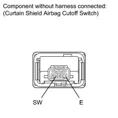
(a) Turn the engine switch off.
(b) Disconnect the cable from the negative (-) battery terminal, and wait for at least 90 seconds.
(c) Remove the curtain shield airbag cutoff switch
.
(d) Measure the resistance according to the value(s) in the table below.
Standard Resistance:
|
Tester Connection |
Switch Condition |
Specified Condition |
|---|---|---|
|
4 (SW) - 1 (E) |
Curtain shield airbag cutoff switch is in on position |
Below 1 Ω |
|
4 (SW) - 1 (E) |
Curtain shield airbag cutoff switch is in off position |
1 MΩ or higher |
|
|
4. |
CHECK CURTAIN SHIELD AIRBAG CUTOFF SWITCH CIRCUIT |
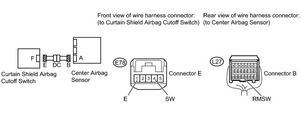
(a) Turn the engine switch off.
(b) Disconnect the cable from the negative (-) battery terminal, and wait for at least 90 seconds.
(c) Disconnect the connector from the center airbag sensor and curtain shield airbag cutoff switch.
(d) Measure the resistance according to the value(s) in the table below.
Standard Resistance:
|
Tester Connection |
Condition |
Specified Condition |
|---|---|---|
|
L27-21 (RMSW) - E78-4 (SW) |
Always |
Below 1 Ω |
|
E78-4 (SW) - Body ground |
Always |
1 MΩ or higher |
|
E78-1 (E) - Body ground |
Always |
Below 1 Ω |
(e) Connect the cable to the negative (-) battery terminal, and wait for at least 2 seconds.
(f) Measure the voltage according to the value(s) in the table below.
Standard Voltage:
|
Tester Connection |
Switch Condition |
Specified Condition |
|---|---|---|
|
E78-4 (SW) - Body ground |
Engine switch on (IG) |
Below 1 V |
|
E78-1 (E) - Body ground |
Engine switch on (IG) |
Below 1 V |
|
|
5. |
CHECK FLOOR WIRE (CENTER AIRBAG SENSOR - INSTRUMENT PANEL WIRE) |
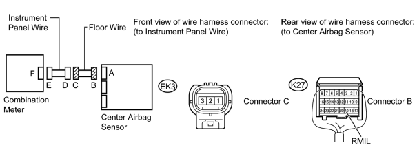
(a) Turn the engine switch off.
(b) Disconnect the cable from the negative (-) battery terminal, and wait for at least 90 seconds.
(c) Disconnect the floor wire connector from the instrument panel wire.
(d) Measure the resistance according to the value(s) in the table below.
Standard Resistance:
|
Tester Connection |
Condition |
Specified Condition |
|---|---|---|
|
EK3-3 - K27-19 (RMIL) |
Always |
Below 1 Ω |
|
EK3-3 - Body ground |
Always |
1 MΩ or higher |
(e) Connect the cable to the negative (-) battery terminal, and wait for at least 2 seconds.
(f) Measure the voltage according to the value(s) in the table below.
Standard Voltage:
|
Tester Connection |
Switch Condition |
Specified Condition |
|---|---|---|
|
EK3-3 - Body ground |
Engine switch on (IG) |
Below 1 V |
|
|
6. |
CHECK NO. 2 FLOOR WIRE (CENTER AIRBAG SENSOR - INSTRUMENT PANEL WIRE) |
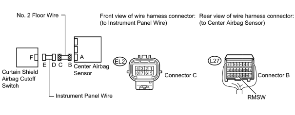
(a) Turn the engine switch off.
(b) Disconnect the cable from the negative (-) battery terminal, and wait for at least 90 seconds.
(c) Disconnect the No. 2 floor wire connector from the instrument panel wire.
(d) Measure the resistance according to the value(s) in the table below.
Standard Resistance:
|
Tester Connection |
Condition |
Specified Condition |
|---|---|---|
|
EL2-4 - L27-21 (RMSW) |
Always |
Below 1 Ω |
|
EL2-4 - Body ground |
Always |
1 MΩ or higher |
(e) Connect the cable to the negative (-) battery terminal, and wait for at least 2 seconds.
(f) Measure the voltage according to the value(s) in the table below.
Standard Voltage:
|
Tester Connection |
Switch Condition |
Specified Condition |
|---|---|---|
|
EL2-4 - Body ground |
Engine switch on (IG) |
Below 1 V |
|

|

|