| Last Modified: 11-27-2007 | 1.6 A | |
| Service Category: Vehicle Exterior | Section: Exterior Panels/Trim | |
| Model Year: 2008 | Model: LX570 | Doc ID: RM0000038JV003X |
| Title: EXTERIOR PANELS / TRIM: FRONT BUMPER: INSTALLATION (2008 LX570) | ||
INSTALLATION
HINT:
A bolt without a torque specification is shown in the standard bolt chart
 .
.
1. INSTALL FRONT UPPER CENTER BUMPER RETAINER
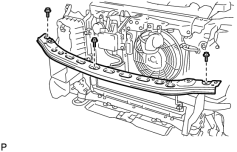
(a) Install the bumper retainer with the 3 bolts.
2. INSTALL HEADLIGHT ASSEMBLY LH
3. INSTALL HEADLIGHT ASSEMBLY RH
HINT:
Use the same procedures described for the LH side.
4. INSTALL FRONT BUMPER SIDE SUPPORT LH
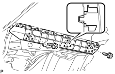
(a) Attach the 3 clips to install the side support.
(b) Install the 2 screws.
5. INSTALL FRONT BUMPER SIDE SUPPORT RH
HINT:
Use the same procedures described for the LH side.
6. INSTALL FRONT NO. 2 BUMPER EXTENSION SUB-ASSEMBLY LH
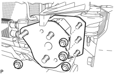
(a) Install the bumper extension with the 4 nuts.
Torque: 67 N·m (683 kgf·cm, 49 ft·lbf)
7. INSTALL FRONT NO. 2 BUMPER EXTENSION SUB-ASSEMBLY RH
HINT:
Use the same procedures described for the LH side.
8. INSTALL FRONT BUMPER REINFORCEMENT SUB-ASSEMBLY
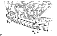
(a) Install the reinforcement with the 6 nuts.
Torque: 71 N·m (724 kgf·cm, 52 ft·lbf)
9. INSTALL FRONT BUMPER MOUNTING BRACKET LH
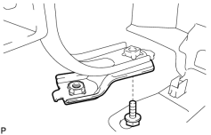
(a) Install the bracket with the bolt.
10. INSTALL FRONT BUMPER MOUNTING BRACKET RH
HINT:
Use the same procedures described for the LH side.
11. INSTALL FRONT BUMPER ENERGY ABSORBER
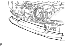
(a) Install the energy absorber.
12. INSTALL FRONT BUMPER COVER
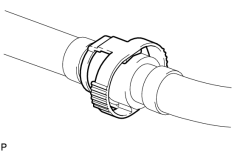
(a) w/ Headlight Cleaner System:
Connect the headlight cleaner hose.
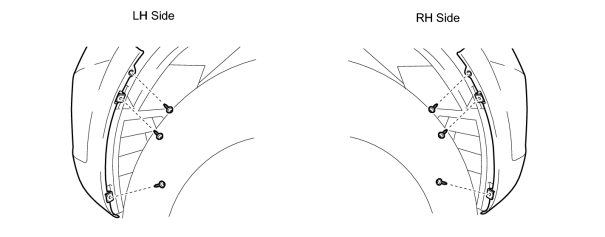
(b) Connect the No. 4 engine room wire connector and attach the 10 claws to install the bumper cover.
(c) Install the 5 clips, 2 screws and 4 bolts.
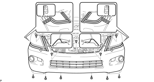
(d) Using a T30 "TORX" socket, install the 6 screws.
13. INSTALL RADIATOR GRILLE ASSEMBLY
14. INSTALL UPPER RADIATOR SUPPORT SEAL
15. INSTALL ENGINE ROOM SIDE COVER LH
16. INSTALL ENGINE ROOM SIDE COVER RH
17. INSTALL FRONT FENDER SPLASH SHIELD SUB-ASSEMBLY LH
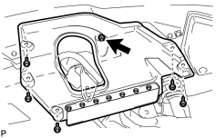
(a) Push in the clip indicated by the arrow in the illustration to install the fender splash shield.
(b) Install the 3 bolts and 2 screws.
18. INSTALL FRONT FENDER SPLASH SHIELD SUB-ASSEMBLY RH
HINT:
Use the same procedures described for the LH side.

|

|