| Last Modified: 11-27-2007 | 1.6 A | |
| Service Category: Steering | Section: Steering Linkage/Steering Gear | |
| Model Year: 2008 | Model: LX570 | Doc ID: RM0000039T1005X |
| Title: STEERING GEAR / LINKAGE: STEERING LINKAGE: REASSEMBLY (2008 LX570) | ||
REASSEMBLY
1. INSTALL STEERING RACK END SUB-ASSEMBLY
(a) Temporarily install the 2 steering rack ends to the power steering rack.
(b) Fill up the ball joint of the steering rack ends with MP grease.
|
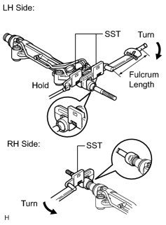
(c) Using SST, install the power steering rack end (RH side) to the power steering rack. SST: 09922-10010 Torque: 147 N·m (1499 kgf·cm, 108 ft·lbf) Torque: 110 N·m (1122 kgf·cm, 81 ft·lbf) HINT:
|
(d) Using SST and a wrench, install the power steering rack end (LH side) to the power steering rack.
SST: 09922-10010
Torque: 147 N·m (1499 kgf·cm, 108 ft·lbf)
Torque: 110 N·m (1122 kgf·cm, 81 ft·lbf)
HINT:
- Rotate SST in the direction shown in the illustration.
- Use a torque wrench with a fulcrum length of 380 mm (15.0 in.).
2. INSTALL NO. 1 STEERING RACK BOOT
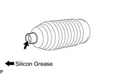
(a) Apply silicon grease to the inside of the small opening of the boot.
(b) Install the 2 boots to the groove on the rack housing.
3. INSTALL STEERING RACK BOOT CLAMP RH
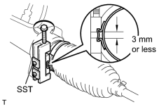
(a) Using SST, install a new boot clamp as shown in the illustration.
SST: 09521-24010
Standard clearance:
3.0 mm (0.119 in.) or less
NOTICE:
Be careful not to damage the boot.
4. INSTALL STEERING RACK BOOT CLAMP LH
HINT:
Use the same procedures described for the RH side.
5. INSTALL STEERING RACK BOOT CLIP RH
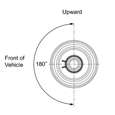
(a) Using pliers, install the boot clip.
NOTICE:
Make sure that the claws of each clip are positioned within the area shown in the illustration.
6. INSTALL STEERING RACK BOOT CLIP LH
HINT:
Use the same procedures described for the RH side.

|

|