| Last Modified: 11-27-2007 | 1.6 G | |
| Service Category: Steering | Section: Steering Linkage/Steering Gear | |
| Model Year: 2008 | Model: LX570 | Doc ID: RM0000039TB005X |
| Title: STEERING GEAR / LINKAGE: STEERING LINKAGE: INSPECTION (2008 LX570) | ||
INSPECTION
1. INSPECT TIE ROD END SUB-ASSEMBLY LH
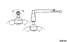
(a) Install the nut.
(b) Flip the ball joint stud back and forth 5 times as shown in the illustration.
(c) Using a torque wrench, turn the nut continuously at a rate of 3 to 5 seconds per turn and check the torque reading on the 5th turn.
Turning torque:
0.981 to 3.432 N*m (10.0 to 35.0 kgf*cm, 8.692 to 30.375 in.*lbf)
HINT:
Make sure the dust cover of the tie rod end ball joint has no cracks or damage. If necessary, replace the tie rod end.
2. INSPECT TOTAL PRELOAD

|
(a) Put matchmarks on the dust cover and steering link. HINT:
Make sure that the steering link is centered when placing matchmarks. |
(b) Remove the dust cover.
(c) Temporarily install the 2 steering rack ends to the power steering rack.
NOTICE:
Do not fully turn the power steering rack without the steering rack ends as it may damage the oil seal in the rack housing.
|
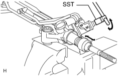
(d) Using SST, fully turn the power steering rack right and left 10 times to settle it. SST: 09616-00011 |
|
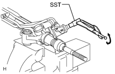
(e) Using SST, turn the control valve and measure the preload. SST: 09616-00011 Standard preload (turning): 2.4 N*m (24 kgf*cm, 21 in.*lbf) If the turning torque is not as specified, replace the power steering link. NOTICE:
After setting the steering rack to the neutral point, align the dust cover rib with the power steering protrusion. HINT:
|
|
|
(f) After inspecting the preload, align the matchmarks and install the dust cover. HINT:
Perform the inspection with the steering link centered. |

|

|