| Last Modified: 11-27-2007 | 1.6 J | |
| Service Category: Vehicle Interior | Section: Theft Deterrent/Keyless Entry | |
| Model Year: 2008 | Model: LX570 | Doc ID: RM000003BI4002X |
| Title: THEFT DETERRENT / KEYLESS ENTRY: THEFT DETERRENT SYSTEM: DESCRIPTION (2008 LX570) | ||
|
Security Horn Circuit |
DESCRIPTION
When the theft deterrent system is operating, the certification ECU (smart key ECU assembly) outputs a signal continuously at 0.4 second intervals, causing the security horn to sound.
WIRING DIAGRAM
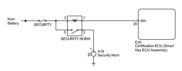
INSPECTION PROCEDURE
PROCEDURE
|
1. |
PERFORM ACTIVE TEST USING TECHSTREAM (SECURITY HORN) |
(a) Operate the Techstream according to the steps on the display and select "Active Test".
Smart Access
|
Tester Display |
Test Part |
Control Range |
Diagnostic Note |
|---|---|---|---|
|
Security Horn |
Security horn |
ON/OFF |
- |
OK:
Security horn operates normally.
|

|
2. |
INSPECT FUSE (SECURITY) |
(a) Remove the SECURITY fuse from the engine room relay block.
(b) Measure the resistance according to the value(s) in the table below.
Standard Resistance:
|
Tester Connection |
Condition |
Specified Condition |
|---|---|---|
|
SECURITY fuse |
Always |
Below 1 Ω |
|
|
3. |
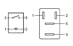
INSPECT SECURITY HORN RELAY |
|
(a) Remove the security horn relay from the engine room relay block. |
(b) Measure the resistance according to the value(s) in the table below.
Standard Resistance:
|
Tester Connection |
Condition |
Specified Condition |
|---|---|---|
|
3 - 5 |
Battery voltage is not applied to terminals 1 and 2 |
10 kΩ or higher |
|
3 - 5 |
Battery voltage is applied to terminals 1 and 2 |
Below 1 Ω |
|
|
4. |
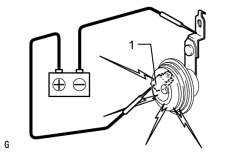
INSPECT SECURITY HORN ASSEMBLY |
|
(a) Remove the security horn
|

(b) Apply battery voltage to the horn and check the operation of the horn.
OK:
|
Measurement Condition |
Specified Condition |
|---|---|
|
Battery positive (+) → Terminal 1 Battery negative (-) → Horn bracket |
Horn sounds |
|
|
5. |
CHECK HARNESS AND CONNECTOR (ENGINE ROOM RELAY BLOCK - CERTIFICATION ECU [SMART KEY ECU ASSEMBLY] AND SECURITY HORN) |
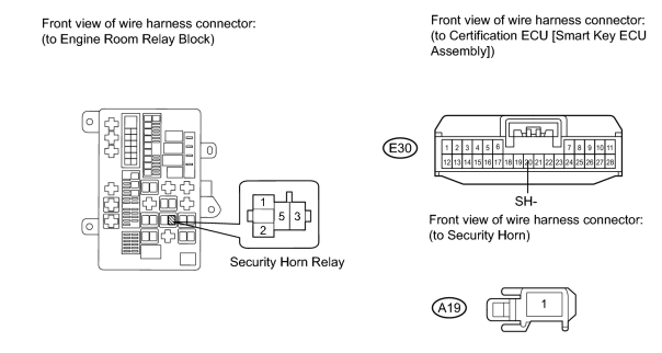
(a) Remove the SECURITY HORN relay from the engine room relay block.
(b) Disconnect the E30 ECU connector.
(c) Disconnect the A19 horn connector.
(d) Measure the resistance according to the value(s) in the table below.
Standard Resistance:
|
Tester Connection |
Condition |
Specified Condition |
|---|---|---|
|
Relay block security horn relay terminal 1 - E30-20 (SH-) |
Always |
Below 1 Ω |
|
Relay block security horn relay terminal 3 - A19-1 |
Always |
Below 1 Ω |
|
E30-20 (SH-) Body ground |
Always |
10 kΩ or higher |
|
A19-1 - Body ground |
Always |
10 kΩ or higher |
(e) Measure the voltage according to the value(s) in the table below.
Standard Voltage:
|
Tester Connection |
Condition |
Specified Condition |
|---|---|---|
|
Relay block security horn relay terminal 2 - Body ground |
Always |
11 to 14 V |
|
Relay block security horn relay terminal 5 - Body ground |
Always |
11 to 14 V |
|

|

|