| Last Modified: 11-27-2007 | 1.6 J | |
| Service Category: Vehicle Interior | Section: Heating/Air Conditioning | |
| Model Year: 2008 | Model: LX570 | Doc ID: RM000003CPO003X |
| Title: HEATING / AIR CONDITIONING: AIR CONDITIONING SYSTEM: DESCRIPTION (2008 LX570) | ||
|
Cooling Box Sensor Circuit |
DESCRIPTION
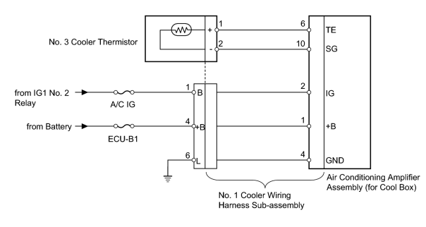
The No. 3 cooler thermistor is installed on the evaporator in the cooling box unit to detect the cooled air temperature that has passed through the evaporator and control the cooling box. It sends appropriate signals to the air conditioning amplifier assembly (for cool box). The resistance of the No. 3 cooler thermistor changes in accordance with the cooled air temperature that has passed through the evaporator. As the temperature decreases, the resistance increases. As the temperature increases, the resistance decreases.
The air conditioning amplifier assembly (for cool box) applies voltage (12 V) to the No. 3 cooler thermistor and reads voltage changes as the resistance of the No. 3 cooler thermistor changes.
WIRING DIAGRAM
INSPECTION PROCEDURE
PROCEDURE
|
1. |
INSPECT FUSE (A/C IG, ECU-B1) |
(a) Remove the A/C IG fuse from the cowl side junction block LH.
(b) Remove the ECU-B1 fuse from the engine room relay block.
(c) Measure the resistance according to the value(s) in the table below.
Standard Resistance:
|
Tester Connection |
Condition |
Specified Condition |
|---|---|---|
|
ECU-B1 fuse |
Always |
Below 1 Ω |
|
A/C IG fuse |
|

|
2. |
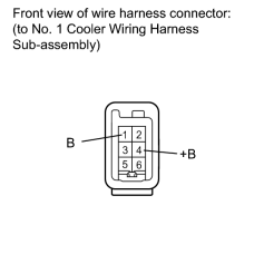
CHECK HARNESS AND CONNECTOR (NO. 1 COOLER WIRING HARNESS - BATTERY) |
|
(a) Disconnect the No. 1 cooler wiring harness sub-assembly connector. |
(b) Measure the voltage according to the value(s) in the table below.
Standard Voltage:
|
Tester Connection |
Switch Condition |
Specified Condition |
|---|---|---|
|
4 (+B) - Body ground |
Always |
11 to 14 V |
|
1 (B) - Body ground |
Engine switch off |
Below 1 V |
|
Engine switch on (IG) |
11 to 14 V |
|
|
3. |
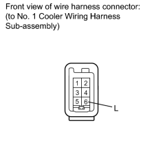
CHECK HARNESS AND CONNECTOR (NO. 1 COOLER WIRING HARNESS - BODY GROUND) |
|
(a) Disconnect the No. 1 cooler wiring harness sub-assembly connector. |
(b) Measure the resistance according to the value(s) in the table below.
Standard Resistance:
|
Tester Connection |
Condition |
Specified Condition |
|---|---|---|
|
6 (L) - Body ground |
Always |
Below 1 Ω |
|
|
4. |
CHECK NO. 1 COOLER WIRING HARNESS SUB-ASSEMBLY (OPERATION) |
(a) Replace the No. 1 cooler wiring harness sub-assembly with a normal one and check that the condition returns to normal.
OK:
Same problem does not occur.
|
|
5. |
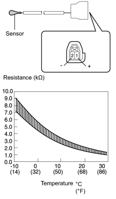
CHECK NO. 3 COOLER THERMISTOR |
|
(a) Remove the No. 3 cooler thermistor
|

(b) Measure the resistance according to the value(s) in the table below.
Standard Resistance:
|
Tester Connection |
Condition |
Specified Condition |
|---|---|---|
|
1 (+) - 2 (-) |
-10°C (14°F) |
7.30 to 9.10 kΩ |
|
-5°C (23°F) |
5.65 to 6.95 kΩ |
|
|
0°C (32°F) |
4.40 to 5.35 kΩ |
|
|
5°C (41°F) |
3.40 to 4.15 kΩ |
|
|
10°C (50°F) |
2.70 to 3.25 kΩ |
|
|
15°C (59°F) |
2.14 to 2.58 kΩ |
|
|
20°C (68°F) |
1.71 to 2.05 kΩ |
|
|
25°C (77°F) |
1.38 to 1.64 kΩ |
|
|
30°C (86°F) |
1.11 to 1.32 kΩ |
NOTICE:
- Even slightly touching the sensor may change the resistance value. Be sure to hold the connector of the sensor.
- When measuring, the sensor temperature must be the same as the ambient temperature.
HINT:
As the temperature increases, the resistance decreases (See the graph).
|

|

|