| Last Modified: 11-27-2007 | 1.6 J | |
| Service Category: Vehicle Interior | Section: Heating/Air Conditioning | |
| Model Year: 2008 | Model: LX570 | Doc ID: RM000003CPP003X |
| Title: HEATING / AIR CONDITIONING: AIR CONDITIONING SYSTEM: DESCRIPTION (2008 LX570) | ||
|
Cooling Box Control Switch Circuit |
DESCRIPTION
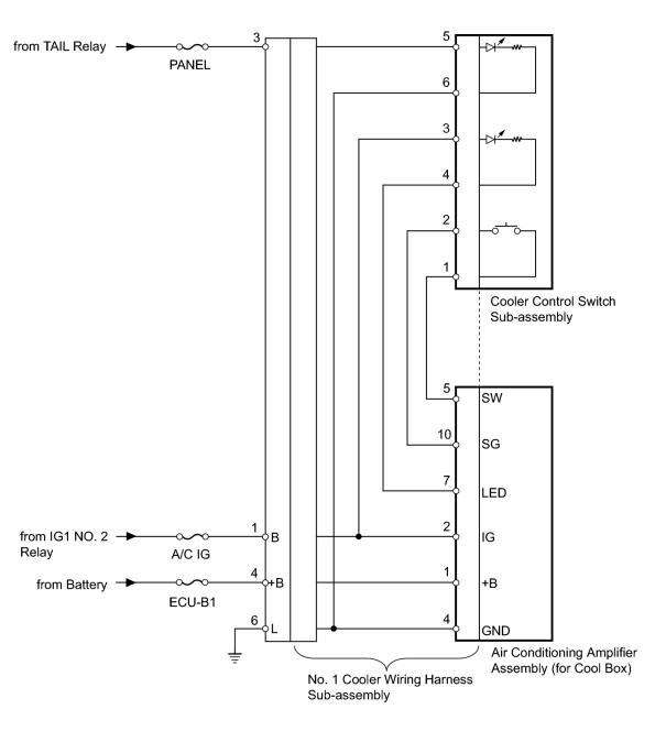
The cooler control switch sub-assembly is the activation switch for the cool box. If the cool box does not activate when the cooler control switch sub-assembly is pushed, there may be a malfunction in the circuit shown below.
WIRING DIAGRAM
INSPECTION PROCEDURE
PROCEDURE
|
1. |
INSPECT FUSE (PANEL, A/C IG, ECU-B1) |
(a) Remove the PANEL and A/C IG fuses from the cowl side junction block LH.
(b) Remove the ECU-B1 fuse from the engine room relay block.
(c) Measure the resistance according to the value(s) in the table below.
Standard Resistance:
|
Tester Connection |
Condition |
Specified Condition |
|---|---|---|
|
PANEL fuse |
Always |
Below 1 Ω |
|
ECU-B1 fuse |
Always |
Below 1 Ω |
|
A/C IG fuse |
Always |
Below 1 Ω |
|

|
2. |
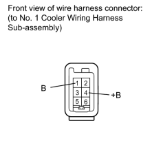
CHECK HARNESS AND CONNECTOR (NO. 1 COOLER WIRING HARNESS - BATTERY) |
|
(a) Disconnect the No. 1 cooler wiring harness sub-assembly connector. |
(b) Measure the voltage according to the value(s) in the table below.
Standard Voltage:
|
Tester Connection |
Switch Condition |
Specified Condition |
|---|---|---|
|
4 (+B) - Body ground |
Always |
11 to 14 V |
|
3 - Body ground |
Always |
11 to 14 V |
|
1 (B) - Body ground |
Engine switch off |
Below 1 V |
|
Engine switch on (IG) |
11 to 14 V |
|
|
3. |
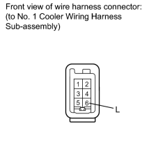
CHECK HARNESS AND CONNECTOR (NO. 1 COOLER WIRING HARNESS - BODY GROUND) |
|
(a) Disconnect the No. 1 cooler wiring harness sub-assembly connector. |
(b) Measure the resistance according to the value(s) in the table below.
Standard Resistance:
|
Tester Connection |
Condition |
Specified Condition |
|---|---|---|
|
6 (L) - Body ground |
Always |
Below 1 Ω |
|
|
4. |
CHECK NO. 1 COOLER WIRING HARNESS SUB-ASSEMBLY (OPERATION) |
(a) Replace the No. 1 cooler wiring harness sub-assembly with a normal one and check that the condition returns to normal.
OK:
Same problem does not occur.
|
|
5. |
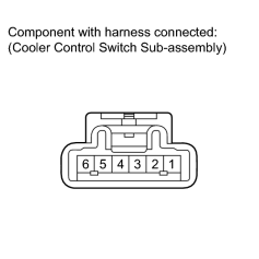
INSPECT COOLER CONTROL SWITCH SUB-ASSEMBLY |
|
(a) Remove the cooler control switch sub-assembly
|

(b) Measure the resistance according to the value(s) in the table below.
Standard Resistance:
|
Tester Connection |
Switch Condition |
Specified Condition |
|---|---|---|
|
1 - 2 |
On |
Below 1 Ω |
|
1 - 2 |
Off |
10 kΩ or higher |
(c) Apply battery voltage to the cooler control switch connector and check that the cooler control switch illuminates.
OK:
|
Measurement Condition |
Specified Condition |
|---|---|
|
Battery positive (+) → Terminal 3 Battery negative (-) → Terminal 4 |
LED illuminates |
|
Battery positive (+) → Terminal 5 Battery negative (-) → Terminal 6 |
LED illuminates |
|

|

|