- Side television camera
- Outer rear view mirror RH
- Harness or connector
- Parking assist ECU
| Last Modified: 11-27-2007 | 1.6 C | |
| Service Category: Audio/Visual/Telematics | Section: Park Assist/Monitoring | |
| Model Year: 2008 | Model: LX570 | Doc ID: RM000003EBI000X |
| Title: PARK ASSIST / MONITORING: SIDE MONITOR SYSTEM: DESCRIPTION (2008 LX570) | ||
|
DTC |
5C-40 |
Camera Picture Error |
DESCRIPTION
|
DTC Code |
DTC Detection Condition |
Trouble Area |
|---|---|---|
|
5C-40 |
Open or short in the side television camera signal circuit. |
|
WIRING DIAGRAM
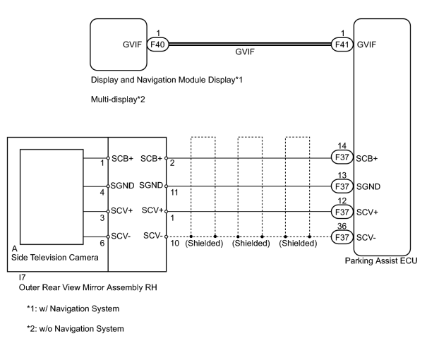
INSPECTION PROCEDURE
PROCEDURE
|
1. |
CHECK PARKING ASSIST ECU |
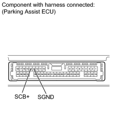
(a) Measure the voltage according to the value(s) in the table below.
Standard Voltage:
|
Tester Connection |
Condition |
Specified Condition |
|---|---|---|
|
F37-14 (SCB+) - F37-13 (SGND) |
Side monitor display screen displayed |
5.8 to 6.5 V |
|

|
2. |
CHECK HARNESS AND CONNECTOR (PARKING ASSIST ECU - OUTER REAR VIEW MIRROR) |
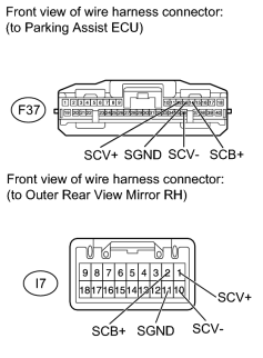
(a) Disconnect the F37 ECU connector.
(b) Disconnect the I7 mirror connector.
(c) Measure the resistance according to the value(s) in the table below.
Standard Resistance:
|
Tester Connection |
Condition |
Specified Condition |
|---|---|---|
|
F37-14 (SCB+) - I7-2 (SCB+) |
Always |
Below 1 Ω |
|
F37-13 (SGND) - I7-11 (SGND) |
Always |
Below 1 Ω |
|
F37-12 (SCV+) - I7-1 (SCV+) |
Always |
Below 1 Ω |
|
F37-36 (SCV-) - I7-10 (SCV-) |
Always |
Below 1 Ω |
|
F37-14 (SCB+) - Body ground |
Always |
10 kΩ or higher |
|
F37-13 (SGND) - Body ground |
Always |
10 kΩ or higher |
|
F37-12 (SCV+) - Body ground |
Always |
10 kΩ or higher |
|
F37-36 (SCV-) - Body ground |
Always |
10 kΩ or higher |
|
|
3. |
INSPECT OUTER REAR VIEW MIRROR ASSEMBLY RH |
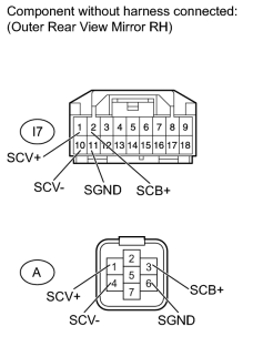
(a) Remove the outer rear view mirror RH
 .
.
(b) Disconnect the side television camera connector.
(c) Measure the resistance according to the value(s) in the table below.
Standard Resistance:
|
Tester Connection |
Condition |
Specified Condition |
|---|---|---|
|
I7-2 (SCB+) - A-1 (SCB+) |
Always |
Below 1 Ω |
|
I7-11 (SGND) - A-4 (SGND) |
Always |
Below 1 Ω |
|
I7-1 (SCV+) - A-3 (SCV+) |
Always |
Below 1 Ω |
|
I7-10 (SCV-) - A-6 (SCV-) |
Always |
Below 1 Ω |
|
|
4. |
CHECK SIDE TELEVISION CAMERA ASSEMBLY |
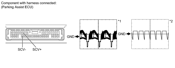
(a) Using an oscilloscope, check the waveform.
Measurement Condition
|
Item |
Content |
|---|---|
|
Terminal No. (Symbol) |
F37-12 (SCV+) - F37-36 (SCV-) |
|
Tool Setting |
|
|
Condition |
|
|
|
5. |
REPLACE HARNESS AND CONNECTOR (GVIF CABLE) |
(a) Replace the harness and connector (GVIF cable).
|
|
6. |
CHECK DTC OUTPUT |
(a) Clear the DTCs
.
(b) Recheck for DTCs
.
OK:
DTC 5C-40 is not output.
|

|

|