| Last Modified: 11-27-2007 | 1.6 U | |
| Service Category: Vehicle Exterior | Section: Door/Hatch | |
| Model Year: 2008 | Model: LX570 | Doc ID: RM000003EBT000X |
| Title: DOOR / HATCH: POWER BACK DOOR SYSTEM: TERMINALS OF ECU (2008 LX570) | ||
TERMINALS OF ECU
1. CHECK POWER BACK DOOR UNIT
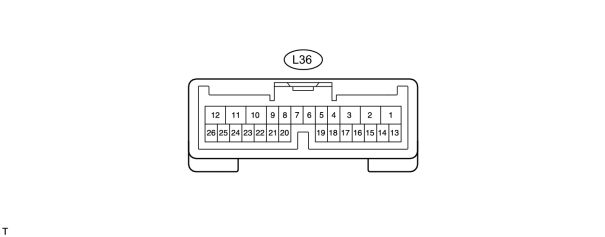
(a) Disconnect the L36 unit connector.
(b) Measure the voltage and resistance according to the value(s) in the table below.
|
Terminal No. (Symbol) |
Wiring Color |
Terminal Description |
Condition |
Specified Condition |
|---|---|---|---|---|
|
L36-12 (B) - Body ground |
B - Body ground |
B power supply |
Always |
11 to 14 V |
|
L36-8 (IG) - Body ground |
G - Body ground |
IG power supply |
Engine switch on (IG) |
11 to 14 V |
|
L36-8 (IG) - Body ground |
G - Body ground |
IG power supply |
Engine switch off |
Below 1 V |
|
L36-10 (ECUB) - Body ground |
R - Body ground |
ECUB power supply |
Always |
11 to 14 V |
|
L36-15 (OSL) - L36-14 (OSE) |
G - BR |
Power back door sensor LH circuit |
Power back door sensor LH not pressed |
Approximately 1 kΩ |
|
L36-15 (OSL) - L36-14 (OSE) |
G - BR |
Power back door sensor LH circuit |
Power back door sensor LH pressed |
Below 100 Ω |
|
L36-13 (OSR) - L36-14 (OSE) |
Y - BR |
Power back door sensor RH circuit |
Power back door sensor RH not pressed |
Approximately 1 kΩ |
|
L36-13 (OSR) - L36-14 (OSE) |
Y - BR |
Power back door sensor RH circuit |
Power back door sensor RH pressed |
Below 100 Ω |
|
L36-11 (GND) - Body ground |
W-B - Body ground |
Body ground |
Always |
Below 1 Ω |
|
L36-17 (MSW) - Body ground |
G - Body ground |
Power back door main switch signal circuit |
Power back door main switch not pushed (on) |
Below 1 Ω |
|
L36-17 (MSW) - Body ground |
G - Body ground |
Power back door main switch signal circuit |
Power back door main switch pushed (off) |
10 kΩ or higher |
|
L36-4 (DS1) - Body ground |
R - Body ground |
Back door control switch signal circuit |
Back door control switch on |
Below 1 Ω |
|
L36-4 (DS1) - Body ground |
R - Body ground |
Back door control switch signal circuit |
Back door control switch off |
10 kΩ or higher |
If the result is not as specified, there may be a malfunction on the wire harness side.
(c) Reconnect the L36 unit connector.
(d) Measure the voltage according to the value(s) in the table below.
|
Terminal No. (Symbol) |
Wiring Color |
Terminal Description |
Condition |
Specified Condition |
|---|---|---|---|---|
|
L36-26 (BZR+) - Body ground |
L - Body ground |
Power back door warning buzzer signal input |
Power back door warning buzzer sounding |
Pulse generation (see waveform 1) |
|
L36-26 (BZR+) - Body ground |
L - Body ground |
Power back door warning buzzer signal input |
Power back door warning buzzer stopped |
Below 1 V |
|
L36-2 (DC+) - L36-1 (DC-) |
R - B |
Power back door lock motor circuit |
Power back door lock motor operating |
11 to 14 V |
|
L36-2 (DC+) - L36-1 (DC-) |
R - B |
Power back door lock motor circuit |
Power back door lock motor stopped |
Below 1 V |
|
L36-17 (MSW) - Body ground |
G - Body ground |
Power back door main switch signal circuit |
Power back door main switch not pushed (on) |
Below 1 V |
|
L36-17 (MSW) - Body ground |
G - Body ground |
Power back door main switch signal circuit |
Power back door main switch pushed (off) |
Pulse generation (see waveform 2) |
|
L36-20 (FUL) - Body ground |
W - Body ground |
Back door courtesy switch signal circuit |
Back door opened |
Below 1 V |
|
L36-20 (FUL) - Body ground |
W - Body ground |
Back door courtesy switch signal circuit |
Back door closed |
Pulse generation (see waveform 3) |
|
L36-4 (DS1) - Body ground |
R - Body ground |
Back door control switch signal circuit |
Back door control switch on |
Below 1 V |
|
L36-4 (DS1) - Body ground |
R - Body ground |
Back door control switch signal circuit |
Back door control switch off |
Pulse generation (see waveform 4) |
|
L36-22 (HAF) - Body ground |
G - Body ground |
Back door lock half-latch switch signal circuit |
Back door opened |
Below 1 V |
|
L36-22 (HAF) - Body ground |
G - Body ground |
Back door lock half-latch switch signal circuit |
Back door closed |
Pulse generation (see waveform 5) |
|
L36-24 (POS) - Body ground |
B - Body ground |
Back door lock position switch signal circuit |
Back door closed |
Below 1 V |
|
L36-24 (POS) - Body ground |
B - Body ground |
Back door lock position switch signal circuit |
Back door opened |
Pulse generation (see waveform 6) |
|
L36-23 (CYLH) - Body ground |
G - Body ground |
Lower tail gate courtesy switch LH circuit |
Lower tail gate opened |
Below 1 V |
|
L36-23 (CYLH) - Body ground |
G - Body ground |
Lower tail gate courtesy switch LH circuit |
Lower tail gate closed |
Pulse generation (see waveform 7) |
|
L36-7 (CYRH) - Body ground |
Y - Body ground |
Lower tail gate courtesy switch RH circuit |
Lower tail gate opened |
Below 1 V |
|
L36-7 (CYRH) - Body ground |
Y - Body ground |
Lower tail gate courtesy switch RH circuit |
Lower tail gate closed |
Pulse generation (see waveform 8) |
If the result is not as specified, the unit may have a malfunction.
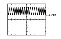
|
(e) Using an oscilloscope, check waveform 1.
|
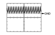
|
(f) Using an oscilloscope, check waveform 2.
|
|
|
(g) Using an oscilloscope, check waveform 3.
|
|
|
(h) Using an oscilloscope, check waveform 4.
|
|
|
(i) Using an oscilloscope, check waveform 5.
|
|
|
(j) Using an oscilloscope, check waveform 6.
|
|
|
(k) Using an oscilloscope, check waveform 7.
|
|
|
(l) Using an oscilloscope, check waveform 8.
|
2. CHECK MAIN BODY ECU
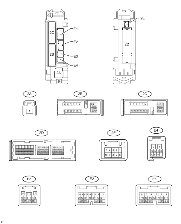
(a) Disconnect the 2B, 2D, E2 and E3 ECU connectors.
(b) Measure the voltage and resistance according to the value(s) in the table below.
|
Terminal No. (Symbol) |
Wiring Color |
Terminal Description |
Condition |
Specified Condition |
|---|---|---|---|---|
|
2B-20 (BATB) - Body ground |
L - Body ground |
Battery power supply |
Always |
11 to 14 V |
|
2D-1 (ACC) - Body ground |
B - Body ground |
Power supply |
Always |
11 to 14 V |
|
E2-2 (PBDS) - Body ground |
R - Body ground |
Power back door control switch circuit |
Power back door control switch pushed (on) |
Below 1 Ω |
|
E2-2 (PBDS) - Body ground |
R - Body ground |
Power back door control switch circuit |
Power back door control switch not pushed (off) |
10 kΩ or higher |
|
2D-62 (GND2) - Body ground |
W-B - Body ground |
Ground |
Always |
Below 1 Ω |
|
E3-1 (GND3) - Body ground |
BR - Body ground |
Ground |
Always |
Below 1 Ω |
If the result is not as specified, there may be a malfunction in the wire harness.
(c) Reconnect the 2B, 2D, E2 and E3 ECU connectors.
(d) Measure the voltage according to the value(s) in the table below.
|
Terminal No. (Symbol) |
Wiring Color |
Terminal Description |
Condition |
Specified Condition |
|---|---|---|---|---|
|
E2-2 (PBDS) - Body ground |
R - Body ground |
Power back door control switch circuit |
Power back door control switch pushed (on) |
Below 1 V |
|
E2-2 (PBDS) - Body ground |
R - Body ground |
Power back door control switch circuit |
Power back door control switch not pushed (off) |
Pulse generation (see waveform) |
If the result is not as specified, the ECU may have a malfunction.
|
|
(e) Using an oscilloscope, check waveform.
|

|

|