| Last Modified: 11-27-2007 | 1.6 U | |
| Service Category: Power Source/Network | Section: Networking | |
| Model Year: 2008 | Model: LX570 | Doc ID: RM000003ERN000X |
| Title: NETWORKING: CAN COMMUNICATION SYSTEM: SYSTEM DIAGRAM (2008 LX570) | ||
SYSTEM DIAGRAM
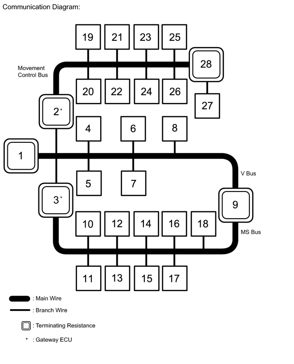
|
No. |
ECU/Sensor Name |
|---|---|
|
1 |
ECM |
|
2 |
Network Gateway ECU |
|
3 |
Main Body ECU (Cowl Side Junction Block LH) |
|
4 |
DLC3 |
|
5 |
Air Conditioning Amplifier |
|
6 |
Center Airbag Sensor |
|
7 |
Display and Navigation Module Display*1 Multi-display*2 |
|
8 |
AFS ECU (Headlight Swivel ECU) |
|
9 |
Combination Meter |
|
10 |
Certification ECU (Smart Key ECU) |
|
11 |
Multiplex Tilt and Telescopic ECU |
|
12 |
Outer Mirror Control ECU |
|
13 |
Position Control ECU and Switch |
|
14 |
Tire Pressure Warning ECU |
|
15 |
No. 2 Main Body ECU |
|
16 |
Power Back Door Unit (Back Door ECU)*3 |
|
17 |
Bus Buffer ECU*4 |
|
18 |
Windshield Wiper ECU |
|
19 |
Master Cylinder Solenoid (Skid Control ECU) |
|
20 |
Yaw Rate Sensor |
|
21 |
Steering Angle Sensor |
|
22 |
4WD Control ECU |
|
23 |
Parking Assist ECU*5 |
|
24 |
Seat Belt Control ECU*6 |
|
25 |
Distance Control ECU*6 |
|
26 |
Steering Control ECU |
|
27 |
Suspension Control ECU |
|
28 |
No. 1 CAN Junction Connector |
*1: w/ Navigation System
*2: w/o Navigation System
*3: w/ Power Back Door System
*4: w/ LEXUS Link System
*5: w/ Wide View Front and Side Monitor System
*6: w/ Dynamic Radar Cruise Control System
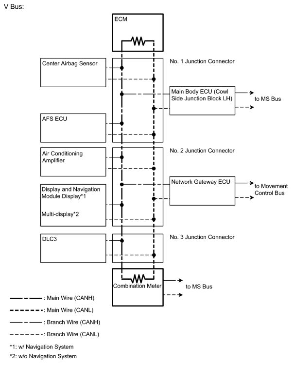
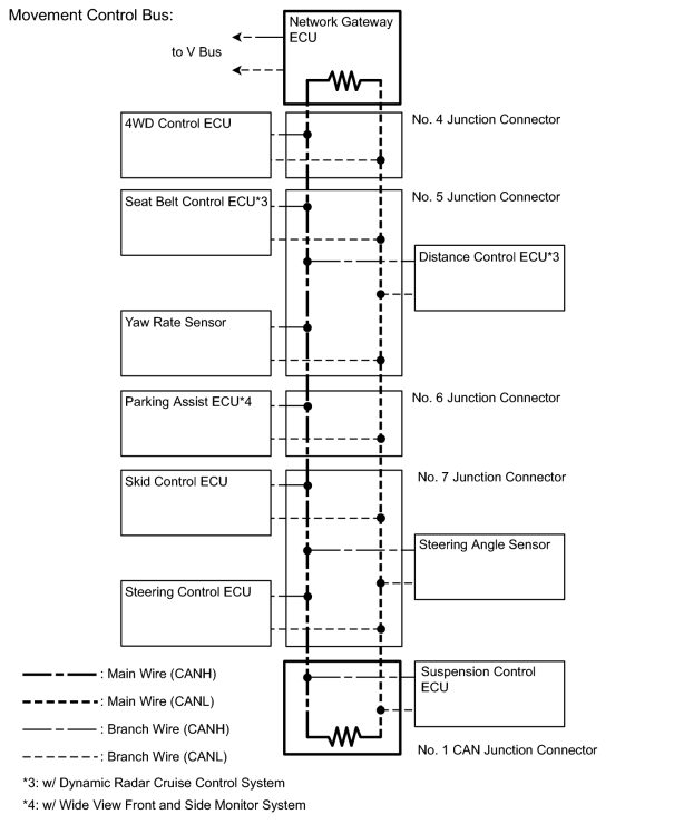
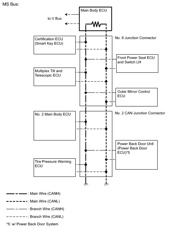
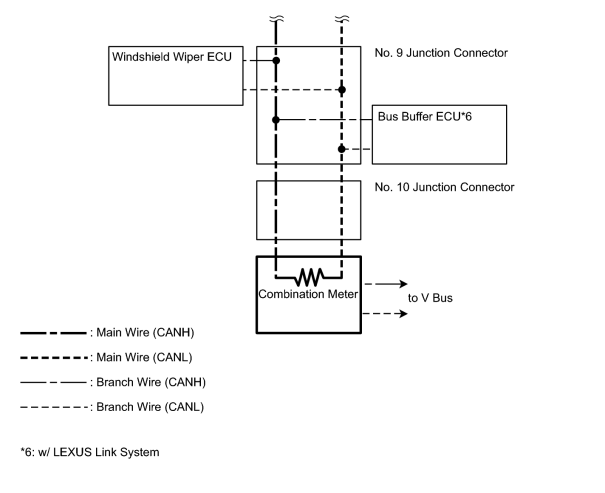
HINT:
- The master cylinder solenoid (skid control ECU) stores steering sensor and yaw rate sensor DTCs and performs DTC communication by receiving information from the steering sensor and yaw rate sensor.
- The ECM uses the CAN communication system to perform DTC communication instead of the conventional communication line (SIL).

|

|