- Power source circuit of No. 2 main body ECU
- No. 2 main body ECU
- No. 2 main body ECU branch wire or connector
| Last Modified: 11-27-2007 | 1.6 C | |
| Service Category: Power Source/Network | Section: Networking | |
| Model Year: 2008 | Model: LX570 | Doc ID: RM000003F7T000X |
| Title: NETWORKING: CAN COMMUNICATION SYSTEM: DESCRIPTION (2008 LX570) | ||
|
DTC |
U0141 |
Lost Communication with Body Control Module "A" |
DESCRIPTION
|
DTC Code |
DTC Detection Condition |
Trouble Area |
|---|---|---|
|
U0141 |
There is no communication from the No. 2 main body ECU. |
|
WIRING DIAGRAM
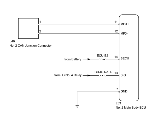
INSPECTION PROCEDURE
PROCEDURE
|
1. |
DISCONNECT CABLE FROM NEGATIVE BATTERY TERMINAL |
(a) Disconnect the cable from the negative (-) battery terminal before measuring the resistances of the main wire and the branch wire.
CAUTION:
Wait at least 90 seconds after disconnecting the cable from the negative (-) battery terminal to disable the SRS system.
NOTICE:
-
w/ Navigation System:
After the engine switch is turned off, the HDD navigation system requires approximately 6 minutes to record various types of memory and settings. As a result, after turning the engine switch off, wait 6 minutes or more before disconnecting the cable from the negative (-) battery terminal.
-
When disconnecting the cable, some systems need to be initialized after the cable is reconnected
 .
.
|

|
2. |
CHECK FOR OPEN IN CAN BUS WIRE (REAR JUNCTION BLOCK BRANCH WIRE) |
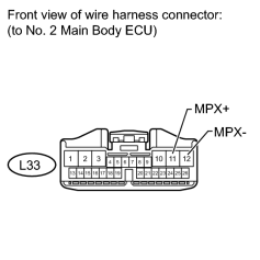
(a) Disconnect the L33 No. 2 main body ECU connector.
(b) Measure the resistance according to the value(s) in the table below.
Standard Resistance:
|
Tester Connection |
Switch Condition |
Specified Condition |
|---|---|---|
|
L33-11 (MPX+) - L33-12 (MPX-) |
Engine switch off |
54 to 69 Ω |
|
|
3. |
CHECK HARNESS AND CONNECTOR (NO. 2 MAIN BODY ECU - BATTERY AND BODY GROUND) |
(a) Connect the cable to the negative (-) battery terminal.
NOTICE:
When disconnecting the cable, some systems need to be initialized after the cable is reconnected
.
|
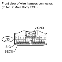
(b) Disconnect the L33 No. 2 main body ECU connector. |
(c) Measure the resistance according to the value(s) in the table below.
Standard Resistance:
|
Tester Connection |
Condition |
Specified Condition |
|---|---|---|
|
L33-7 (GND) - Body ground |
Always |
Below 1 Ω |
(d) Measure the voltage according to the value(s) in the table below.
Standard Voltage:
|
Tester Connection |
Switch Condition |
Specified Condition |
|---|---|---|
|
L33-14 (BECU) - Body ground |
Always |
11 to 14 V |
|
L33-13 (SIG) - Body ground |
Engine switch on (IG) |
11 to 14 V |
|

|

|