| Last Modified: 11-27-2007 | 1.6 J | |
| Service Category: Engine/Hybrid System | Section: Cruise Control | |
| Model Year: 2008 | Model: LX570 | Doc ID: RM000003FZP000X |
| Title: CRUISE CONTROL: DYNAMIC RADAR CRUISE CONTROL SYSTEM: DESCRIPTION (2008 LX570) | ||
|
Millimeter Wave Radar Sensor Power Source Circuit |
DESCRIPTION
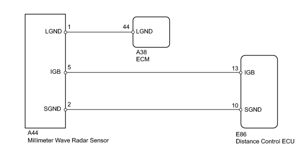
This circuit provides power to the millimeter wave radar sensor. The millimeter wave radar sensor emits radio waves towards an object in front and measures the distance and direction of the object by receiving the wave reflections. Based on the reflections, the sensor calculates the difference in speed between the vehicle and the object in front. This data is transmitted to the distance control ECU.
WIRING DIAGRAM
INSPECTION PROCEDURE
NOTICE:
When the distance control ECU is replaced with a new one, initialization must be performed
 .
.
PROCEDURE
|
1. |
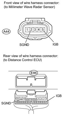
CHECK HARNESS AND CONNECTOR (MILLIMETER WAVE RADAR SENSOR - DISTANCE CONTROL ECU) |
|
(a) Disconnect the A44 millimeter wave radar sensor connector. |
(b) Disconnect the E86 distance control ECU connector.
(c) Measure the resistance according to the value(s) in the table below.
Standard Resistance:
|
Tester Connection |
Condition |
Specified Condition |
|---|---|---|
|
A44-2 (SGND) - E86-10 (SGND) |
Always |
Below 1 Ω |
|
A44-5 (IGB) - E86-13 (IGB) |
||
|
E86-13 (IGB) - Body ground |
Always |
10 kΩ or higher |
|
A44-5 (IGB) - Body ground |
|

|
2. |
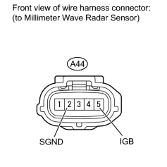
CHECK DISTANCE CONTROL ECU (IGB VOLTAGE) |
|
(a) Disconnect the A44 millimeter wave radar sensor connector. |
(b) Measure the voltage according to the value(s) in the table below.
Standard Voltage:
|
Tester Connection |
Switch Condition |
Specified Condition |
|---|---|---|
|
A44-5 (IGB) - A44-2 (SGND) |
Engine switch on (IG) |
11 to 14 V |
|
|
3. |
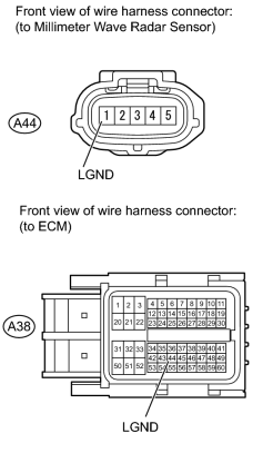
CHECK HARNESS AND CONNECTOR (MILLIMETER WAVE RADAR SENSOR - ECM AND BODY GROUND) |
|
(a) Disconnect the A44 millimeter wave radar sensor connector. |
(b) Disconnect the A38 ECM connector.
(c) Measure the resistance according to the value(s) in the table below.
Standard Resistance:
|
Tester Connection |
Condition |
Specified Condition |
|---|---|---|
|
A44-1 (LGND) - A38-44 (LGND) |
Always |
Below 1 Ω |
|
A44-1 (LGND) - Body ground |
Always |
10 kΩ or higher |
|

|

|