AIRBAG SYSTEM > PRECAUTION |
| System Name | See procedure |
| Lighting System |
Click here
|
| Sliding Roof Control System | |
| Power Window Control System | |
| Power Door Lock Control System | |
| Power Back Door Control System | |
| Back Door Closer System | |
| Electrical Back Door Outside Handle System | |
| SFI System |
| 1.HANDLING PRECAUTIONS FOR AIRBAG SENSORS |
Before starting the following operations, wait for at least 90 seconds after disconnecting the negative (-) terminal cable from the battery:
Replacement of the airbag sensors
Adjustment of the front/rear doors of a vehicle equipped with a side airbag and curtain shield airbag (fitting adjustment)
When connecting or disconnecting the airbag sensor connectors, ensure that each sensor is installed in the vehicle.
Do not use the airbag sensors which have been dropped during the operation or transportation.
Do not disassemble the airbag sensors.
| 2.INSPECTION PROCEDURE FOR VEHICLE INVOLVED IN ACCIDENT |
When the airbag has not deployed, confirm the DTCs by checking the SRS warning light. If there is any malfunction in the SRS airbag system, perform troubleshooting.
When any of the airbags have deployed, replace the airbag sensors and check the installation condition.
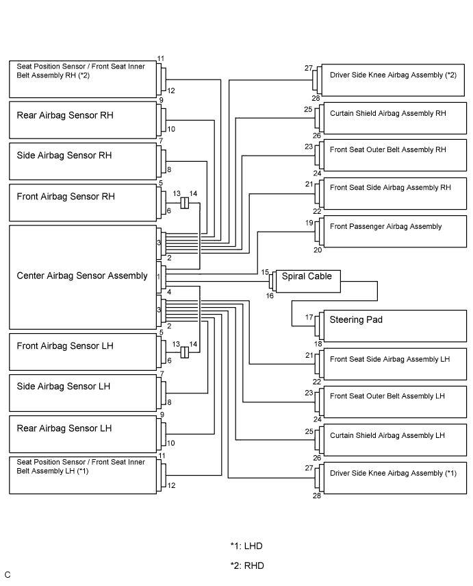
| 3.SRS CONNECTORS |
SRS connectors are located as shown in the following illustration.
| No. | Connector Type | Application |
| (1) | Terminal Twin-Lock Mechanism | Connectors 2, 4, 8, 10, 13, 14, 15, 21, 22 |
| (2) | Activation Prevention Mechanism | Connectors 2, 4, 16, 18, 22, 24, 26, 28 |
| (3) | Electrical Connection Check Mechanism | Connectors 1, 2, 3, 4 |
| (4) | Half Connection Prevention Mechanism | Connectors 6, 8, 10, 13, 15, 21 |
| (5) | Connector Lock Mechanism | Connectors 17, 19, 23, 25, 27 |
| (6) | Connector Position Assurance Mechanism | Connector 6 |
All connectors in the SRS, except the seat position airbag sensor connector, are colored yellow to distinguish them from other connectors. These connectors have special functions, and are specially designed for the SRS. All SRS connectors use durable gold-plated terminals, and are placed in the locations shown on the previous page to ensure high reliability.
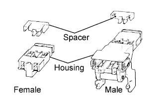 |
Terminal twin-lock mechanism:
All connectors with a terminal twin-lock mechanism have a two-piece component consisting of a housing and a spacer. This design enables the terminal to be locked securely by two locking devices (the retainer and the lance) to prevent terminals from coming out.
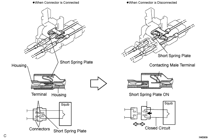
Activation prevention mechanism:
All connectors with an activation prevention mechanism contain a short spring plate. When these connectors are disconnected, the short spring plate creates a short circuit by automatically connecting the positive (+) and negative (-) terminals of the squib.
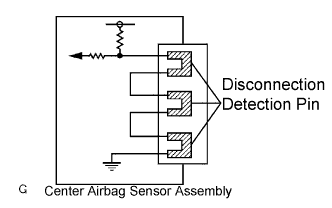 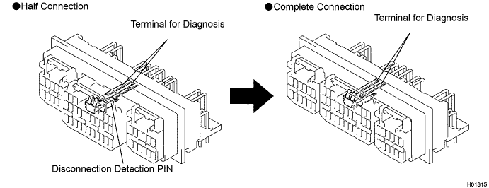 |
Electrical connection check mechanism:
This mechanism electrically checks that the connectors are connected correctly and completely. The electrical connection check mechanism is designed so that the disconnection detection pin connects with the diagnosis terminals when the connector housing lock is locked.
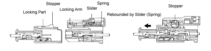
Half connection prevention mechanism:
If the connector is not completely connected, the connector is disconnected due to the spring operation so that no continuity exists.
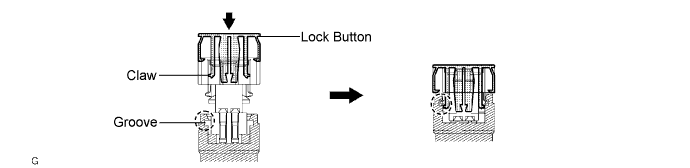
Connector lock mechanism:
Locking the connector lock button connects the connector securely.
Connector position assurance mechanism:
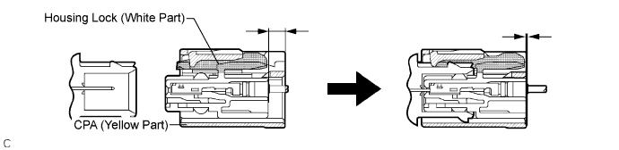
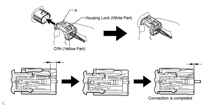
Only when the housing lock (white part) is completely engaged, the CPA (yellow part) slides, which completes the connector engagement.
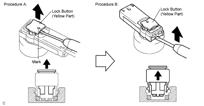
| 4.DISCONNECTION OF CONNECTORS FOR STEERING PAD, FRONT PASSENGER AIRBAG ASSEMBLY, DRIVER SIDE KNEE AIRBAG ASSEMBLY, CURTAIN SHIELD AIRBAG ASSEMBLY AND FRONT SEAT OUTER BELT ASSEMBLY |
Release the lock button (yellow part) of the connector using a screwdriver (Procedure A).
Insert the screwdriver tip between the connector and the base, and then raise the connector (Procedure B).
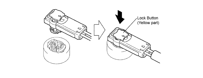
| 5.CONNECTION OF CONNECTORS FOR STEERING PAD, FRONT PASSENGER AIRBAG ASSEMBLY (SQUIB SIDE), DRIVER SIDE KNEE AIRBAG ASSEMBLY, CURTAIN SHIELD AIRBAG ASSEMBLY AND FRONT SEAT OUTER BELT ASSEMBLY |
Connect the connector.
Push down securely on the lock button (yellow part) of the connector. (When locking, a click sound can be heard.)
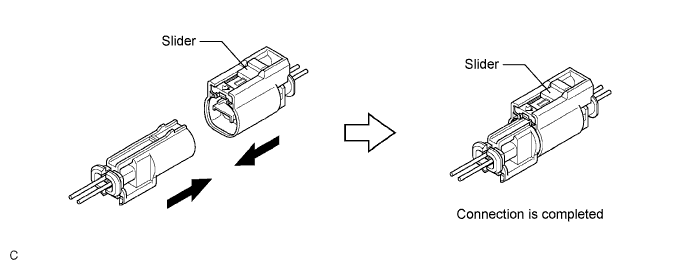
| 6.DISCONNECTION OF CONNECTOR FOR FRONT SEAT AIRBAG ASSEMBLY |
Place a finger on the slider, slide the slider to release the lock, and then disconnect the connector.
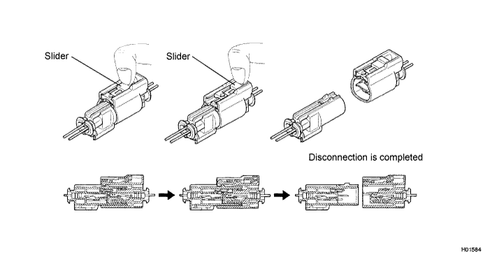
| 7.CONNECTION OF CONNECTOR FOR FRONT SEAT AIRBAG ASSEMBLY |
Connect the connector as shown in the illustration. (When locking, make sure that the slider returns to its original position and a click sound can be heard.)
| 8.DISCONNECTION OF CONNECTOR FOR FRONT AIRBAG SENSOR |
Push down the housing lock (white part) and slide the CPA (yellow part). (At this time, the connector cannot be disconnected yet.)
Push down the housing lock (white part) again and disconnect the connector.
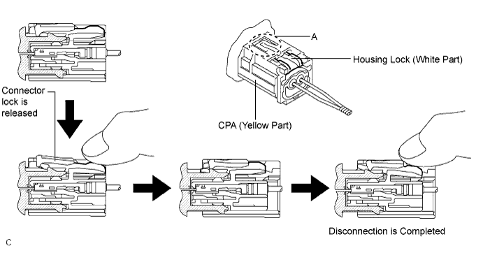
After disconnecting the connector, check that the position of the housing lock (white part) is as shown in the illustration.
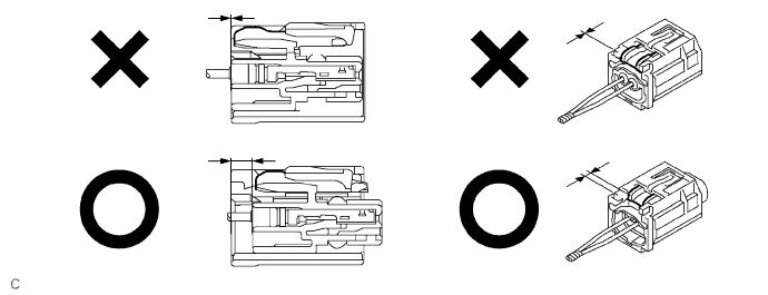
| 9.CONNECTION OF CONNECTOR FOR FRONT AIRBAG SENSOR |
Before connecting the connectors, check that the position of the housing lock (white part) is as shown in the illustration.
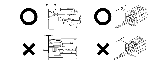
Be sure to engage the connectors until they are locked. (When locking, make sure that a click sound can be heard.)
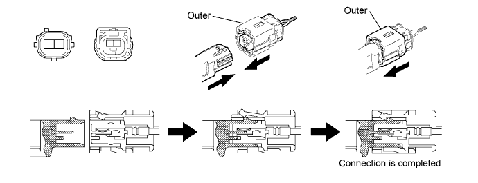
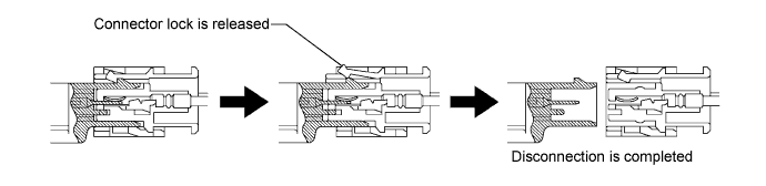
| 10.DISCONNECTION OF CONNECTORS FOR SIDE AIRBAG SENSOR AND REAR AIRBAG SENSOR |
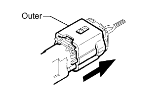 |
While holding both the sides of the outer connector locking sleeve, slide the outer in the direction shown by the arrow.
When the connector lock is released, the connectors are disconnected.
| 11.CONNECTION OF CONNECTORS FOR SIDE AIRBAG SENSOR AND REAR AIRBAG SENSOR |
Connect the connector as shown in the illustration (When locking, make sure that the outer returns to its original position and a click sound can be heard).