BRAKE MASTER CYLINDER > INSTALLATION |
| 1. INSTALL BRAKE MASTER CYLINDER W/SIMULATOR ASSEMBLY (LHD) |
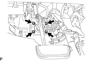 |
Install the gasket and brake master cylinder assembly together with the brake simulator assembly with the 4 nuts.
 |
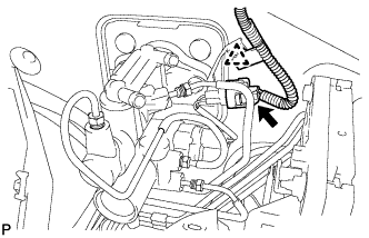
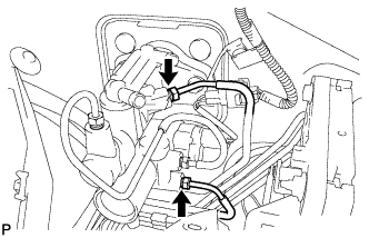
Connect the connector, and engage the clamp.
 |
Use the SST to fully tighten the 2 brake tubes.
| 2. INSTALL BRAKE MASTER CYLINDER W/SIMULATOR ASSEMBLY (RHD) |
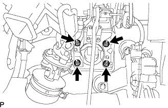 |
Install the gasket and brake master cylinder assembly together with the brake simulator assembly with the 4 nuts.
 |
Connect the connector, and engage the clamp.
 |
Use the SST to fully tighten the 2 brake tubes.
| 3. INSTALL MASTER CYLINDER PUSH ROD CLEVIS |
Apply lithium soap base glycol grease to the push rod pin.
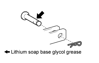 |
Install the push rod clevis to the brake pedal support assembly with the push rod pin and a new clip.
| 4. INSTALL BRAKE PEDAL RETURN SPRING |
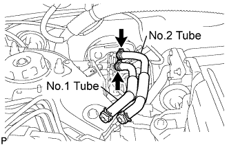
| 5. INSTALL RESERVOIR TUBE NO.2 |
LHD:
 |
Install the reservoir tube No.2 with the clip.
RHD:
 |
Install the reservoir tube No.2 with the clip.
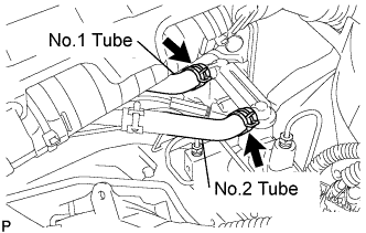
| 6. INSTALL RESERVOIR TUBE NO.1 |
Install the reservoir tube No.1 with the clip.
LHD:
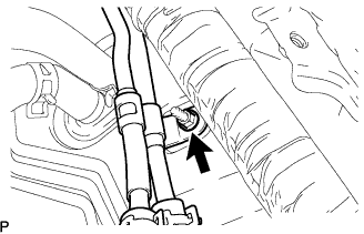 |
Install the nut.
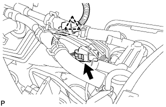
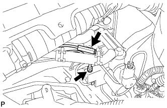
| 7. INSTALL BRAKE MASTER CYLINDER RESERVOIR ASSEMBLY |
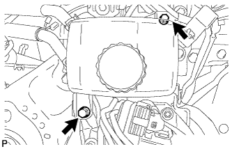 |
Install the brake master cylinder reservoir assembly with the 2 bolts.
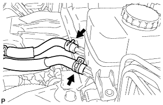 |
Install the 2 reservoir tubes with the 2 clips.
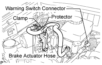 |
Install the brake actuator hose with the 2 clips.
Install the brake actuator hose to the clamp.
Connect the warning switch connector.
| 8. INSTALL COWL TOP PANEL SUB-ASSEMBLY OUTER |
Remove the 4 shock absorber nuts.
 |
Install the 4 bolts, 2 nuts and cowl top panel sub-assembly.
Install the 4 shock absorber nuts (B).
Install the wire harness clamp and grommet (A).
| 9. INSTALL WINDSHIELD WIPER MOTOR AND LINK ASSEMBLY |
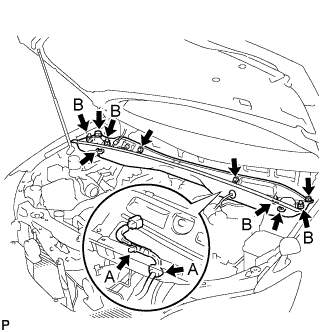
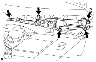 |
Install the windshield wiper motor and link assembly with the 5 bolts.
Connect the connector.
| 10. INSTALL COWL TOP VENTILATOR LOUVER SUB-ASSEMBLY |
| 11. INSTALL FRONT FENDER TO COWL SIDE SEAL LH |
| 12. INSTALL FRONT FENDER TO COWL SIDE SEAL RH |
| 13. INSTALL FRONT WIPER ARM LH |
 |
Operate the front wiper, and stop the front wiper motor at the automatic stop position.
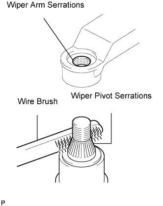
Clean the wiper arm serrations.
Clean the wiper pivot serrations with a wire brush (when reinstalling).
 |
Install the front wiper arm and blade assembly LH with the nut at the position as shown in the illustration.
| 14. INSTALL FRONT WIPER ARM RH |
|
Clean the wiper arm serrations.
Clean the wiper pivot serrations with a wire brush (when reinstalling).
 |
Install the front wiper arm and blade assembly RH with the 2 nuts at the position as shown in the illustration.
Operate the front wipers while spraying water or washer fluid on the windshield.
Make sure that the wipers function properly and there is no interference with the vehicle body.
| 15. CONNECT CABLE TO BATTERY NEGATIVE TERMINAL |
| 16. ADD RESERVOIR WITH BRAKE FLUID |
Add brake fluid to the MAX line in the reservoir.
| 17. BLEED BRAKE ACTUATOR HOSE |
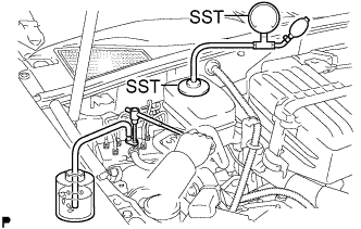 |
Connect SST to the reservoir with the brake reservoir pressure adapter.
Using SST, loosen the bleeder plug of the actuator.
Connect a vinyl tube to the bleeder plug of the actuator.
Use the SST to boost pressure in the reservoir.
Drain approximately 100 cc of fluid.
Tighten the bleeder plug and boost the pressure in the reservoir again (50 to 80 kPa (0.5 to 0.8 kgf/cm2)). Then, loosen the bleeder plug and bleed the brake actuator hose.
When air is completely bled out from the hose between the reservoir and the actuator, tighten the bleeder plug.
| 18. BLEED FRONT BRAKE SYSTEM |
Depress the brake pedal several times and bleed the front brake system from the bleeder plugs on the front brake cylinder RH and LH.
Tighten the bleeder plugs after bleeding.
| 19. INSTALL ABS MOTOR RELAY |
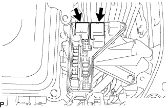 |
Install the 2 ABS motor relays.
| 20. CLEAR DTC |
| 21. PERFORM ACCUMULATOR ZERO DOWN |
Connect the intelligent tester to the DLC3 with the ignition switch off
Depressurize the accumulator.
Check that the parking brake is applied and turn the ignition switch to the ON position.
Turn on the intelligent tester and select "DIAGNOSTIC MENU" → "ABS/VSC" → "ECB UTILITY" → "ZERO DOWN" on the intelligent tester.
When the buzzer sounds, turn the ignition switch off.
Circulate the fluid in the accumulator.
Depressurize the accumulator 5 times.
| 22. CHECK BRAKE FLUID LEVEL IN RESERVOIR |
After performing accumulator zero down (accumulator depressurizing), return the fluid in the accumulator back to the reservoir and then adjust the fluid level in the master cylinder reservoir to the MAX level.
| 23. CLEAR DTC |
| 24. CHECK FOR BRAKE FLUID LEAKAGE |
| 25. CHECK AND ADJUST BRAKE PEDAL HEIGHT |
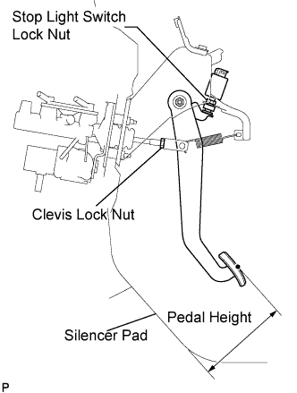 |
Check the brake pedal height.
Adjust the brake pedal height.
Disconnect the connector from the stop light switch assembly.
Loosen the stop light switch lock nut. Turn the switch in order to give the pedal some free play.
Loosen the clevis lock nut.
Adjust the pedal height by turning the pedal push rod.
Tighten the clevis lock nut.
Turn the stop light switch assembly so that the clearance between the nut end and the stop light switch cushion is between 0.5 and 2.4 mm (0.020 to 0.095 in.). Tighten the lock nut.
Connect the connector to the stop light switch assembly.
| 26. ADJUST BRAKE PEDAL STROKE SENSOR ASSEMBLY |
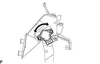 |
Connect the intelligent tester to the DLC3.
Loosen the 2 bolts.
Turn the ignition switch to the ON position. Reading the stroke sensor 1 value shown on the intelligent tester screen, turn the stroke sensor slowly to the right and left to adjust it to the standard voltage.
Tighten the 2 bolts.
Perform system initialization. (Click here)
| 27. CHECK PEDAL FREE PLAY |
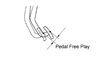 |
Press the pedal until a slight resistance is felt. Measure the distance as shown in the illustration.
If the pedal free play is 1.0 mm (0.039 in.) or less, check the protrusion of the stop light switch assembly shaft.
| 28. CHECK PEDAL RESERVE DISTANCE |
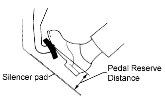 |
Release the parking brake pedal.
With the engine running, depress the pedal and measure the pedal reserve distance as shown in the illustration.
| 29. INSTALL DRIVER SIDE KNEE AIRBAG ASSEMBLY |
Install the driver side knee airbag assembly with the 4 bolts.
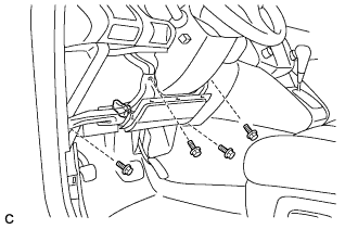 |
Connect the connector to the driver side knee airbag assembly.
| 30. INSTALL INSTRUMENT PANEL FINISH PANEL SUB-ASSEMBLY LOWER |
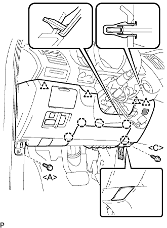 |
Connect the connectors.
Engage the 5 claws and the 4 clips.
Connect the hood lock control cable assembly.
Install the bolt <A>, the screw <C>, and the instrument panel finish panel sub-assembly lower.
| 31. INSTALL FRONT DOOR SCUFF PLATE LH (LHD) |
| 32. INSTALL FRONT DOOR SCUFF PLATE RH (RHD) |
| 33. INSTALL COWL SIDE TRIM ASSEMBLY LH (LHD) |
| 34. INSTALL COWL SIDE TRIM ASSEMBLY RH (RHD) |
| 35. INSPECT SRS WARNING LIGHT |
| 36. PERFORM INITIALIZATION |
