THERMOSTAT > INSTALLATION |
| 1. INSTALL THERMOSTAT |
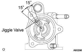 |
Install a new gasket to the thermostat.
Align the jiggle valve of the thermostat and water inlet, and insert the thermostat in the water inlet housing.
| 2. INSTALL WATER INLET |
 |
Install the 3 nuts and the water inlet with the 3 nuts.
| 3. INSTALL WATER INLET PIPE |
 |
Install a new O-ring to the water inlet pipe.
Apply soapy water to the O-ring.
Connect the water inlet pipe to the water inlet.
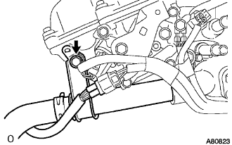
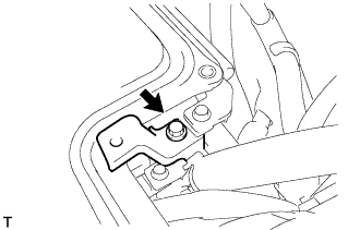
Install the bolt which is used to fix the water inlet pipe to the cylinder head with the bolt.
| 4. INSTALL W/CONVERTER INVERTER ASSEMBLY |
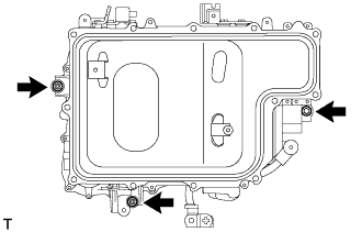 |
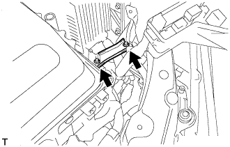
Install the w/ converter inverter assembly with the 2 nuts and bolt.
| 5. INSTALL INVERTER BRACKET NO.4 |
 |
Install the inverter bracket No.4 with the 2 bolts.
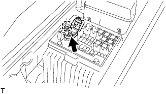
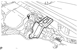
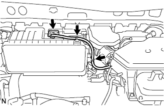
| 6. INSTALL ENGINE ROOM RELAY BLOCK ASSEMBLY |
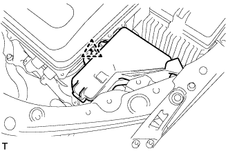 |
Install the engine room relay block assembly.
| 7. REMOVE INVERTER COVER |
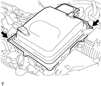 |
Remove the 2 bolts and inverter cover to the w/ converter inverter assembly.
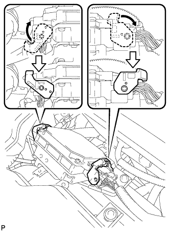
| 8. CONNECT NO.3 WIRE FRAME |
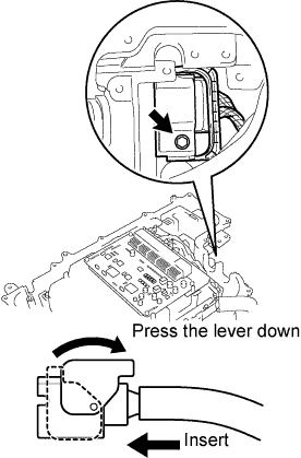 |
After connecting the connector, press the lever down to connect the No.3 wire frame and install the bolt to the w/ converter inverter assembly.
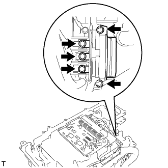 |
Connect the No.3 wire frame (high voltage cable of the rear motor) with the 5 bolts to the w/ converter inverter assembly.
| 9. CONNECT MG ECU CONNECTOR |
 |
Connect the 2 connectors and 2 grommets to the w/ converter inverter assembly.
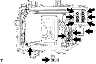
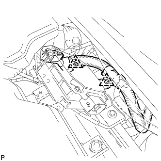
| 10. CONNECT HIGH VOLTAGE CABLE OF FRONT MOTOR |
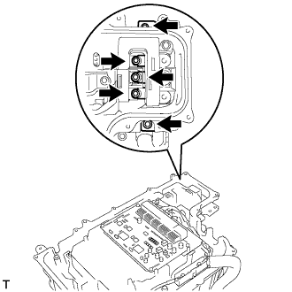 |
Connect the high voltage cable of the Generator with the 5 bolts to the w/ converter inverter assembly.
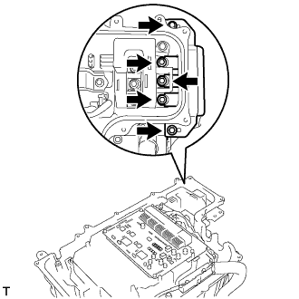 |
Connect the high voltage cable of the Motor with the 5 bolts to the w/ converter inverter assembly.
| 11. CONNECT ENGINE WIRE NO.4 |
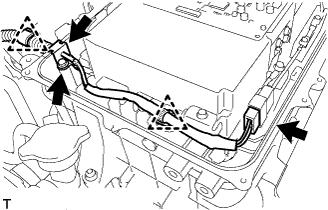 |
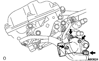
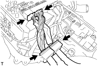
Connect the engine wire No.4 with the connector, clamp and grommet to the w/ converter inverter assembly.
Connect the engine wire No.4 with the bolt to the w/ converter inverter assembly.
| 12. CHECK HIGH VOLTAGE CABLE CONNECTION |
 |
Check that each connector and terminal is firmly installed.
| 13. INSTALL INVERTER COVER |
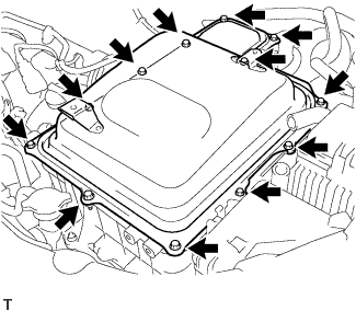 |
Install the inverter cover with the 12 bolts to the w/ converter inverter assembly.
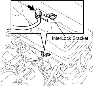 |
Install the interlock bracket with the bolt to the w/ converter inverter assembly.
| 14. INSTALL POWER STEERING ECU BRACKET |
 |
Install the power steering ECU bracket with the bolt to the w/ converter inverter assembly.
| 15. CONNECT WATER HOSE |
 |
Connect the water hose with the clamp to the w/ converter inverter assembly.
| 16. INSTALL INVERTER RESERVE TANK SUB-ASSEMBLY |
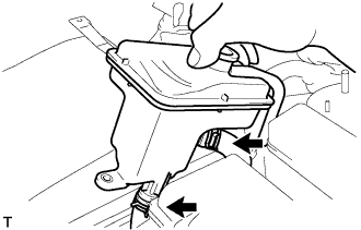 |
Connect the 2 water hoses with the 2 clamps to the inverter reserve tank sub-assembly.
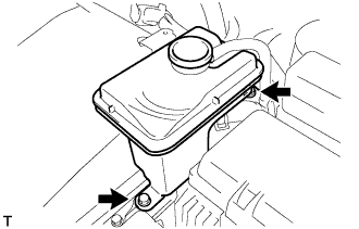 |
Install the inverter reserve tank with the 2 bolts to the w/ converter inverter assembly.
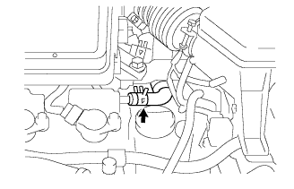
| 17. CONNECT ENGINE ROOM WIRE NO.2 |
 |
Connect the engine room wire No.2 with the nut.
| 18. CONNECT CIRCUIT BREAKER SENSOR NO.1 |
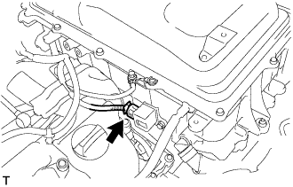 |
Connect the circuit breaker sensor No.1 connector.
| 19. INSTALL POWER STEERING ECU ASSEMBLY |
 |
Install the power steering ECU assembly with the 2 bolts.
 |
Connect the 2 wire harness clamps to the power steering ECU assembly.
 |
Connect the 2 power steering ECU assembly connectors and securely lock the connectors.
 |
Install the ground cable terminal to the power steering ECU assembly with the bolt.
| 20. INSTALL INVERTER BRACKET NO.5 |
 |
Install the inverter bracket No.5 with the bolt.
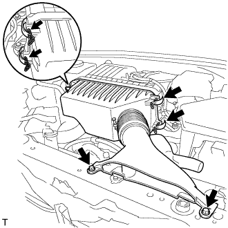
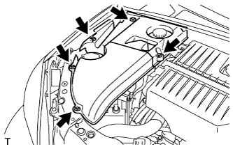
| 21. INSTALL AIR CLEANER W/RESONATER |
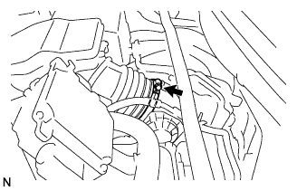 |
Install the air cleaner hose No.1 to the throttle body assembly with the hose clamp.
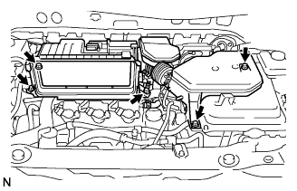 |
Install the air cleaner case w/ resonator with the 5 bolts.
 |
Connect the MAF meter connector.
Connect the 2 wire harness clamps to the air cleaner.
 |
Connect the ventilation hose No.2.
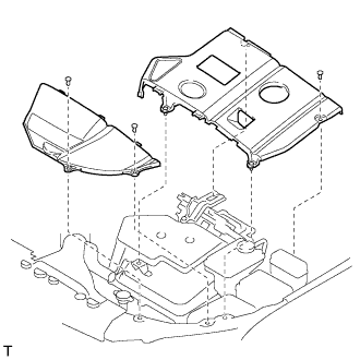
| 22. INSTALL AIR CLEANER CAP W/INLET |
Install the air cleaner filter element to the air cleaner case.
 |
Install the 2 bolts, 4 clamps and air cleaner cap w/ inlet.
| 23. INSTALL COOL AIR INTAKE DUCT SEAL |
Install the 4 clips and cool air intake duct seal.
| 24. INSTALL COWL TOP PANEL SUB-ASSEMBLY OUTER |
Remove the 4 shock absorber nuts.
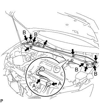 |
Install the 4 bolts, 2 nuts and cowl top panel sub-assembly.
Install the 4 shock absorber nuts (B).
Install the wire harness clamp and grommet (A).
| 25. INSTALL WINDSHIELD WIPER LINK ASSEMBLY |
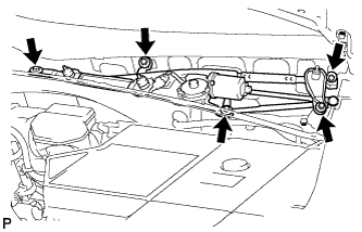 |
Install the windshield wiper motor and link assembly with the 5 bolts.
Connect the connector.
| 26. INSTALL COWL TOP VENTILATOR LOUVER SUB-ASSEMBLY |
| 27. INSTALL FRONT WIPER AND BLADE ASSEMBLY ARM LH |
 |
Operate the front wiper, and stop the front wiper motor at the automatic stop position.
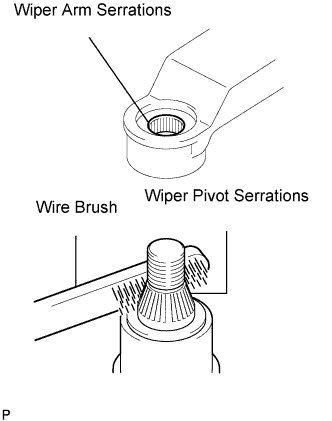
Clean the wiper arm serrations.
Clean the wiper pivot serrations with a wire brush (when reinstalling).
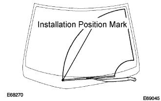 |
Install the front wiper arm and blade assembly LH with the nut at the position as shown in the illustration.
| 28. INSTALL FRONT WIPER AND BLADE ASSEMBLY ARM RH |
|
Clean the wiper arm serrations.
Clean the wiper pivot serrations with a wire brush (when reinstalling).
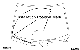 |
Install the front wiper arm and blade assembly RH with the 2 nuts at the position as shown in the illustration.
Operate the front wipers while spraying water or washer fluid on the windshield.
Make sure that the wipers function properly and there is no interference with the vehicle body.
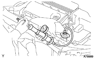
| 29. INSTALL SERVICE PLUG GRIP |
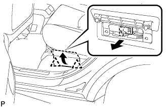 |
Wear insulation gloves, then insert the service plug.
Push down on the grip to lock.
Close the battery service hole cover.
| 30. REMOVE ENGINE ROOM COVER SIDE |
 |
Install the 5 clips and engine room cover side
| 31. INSTALL ENGINE ROOM SIDE LH COVER |
 |
Fit the clips and install the engine room side LH cover.
| 32. CONNECT BATTERY NEGATIVE CABLE |
| 33. ADD HYBRIT VEHICLE COOLANT |
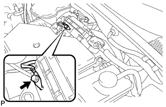
 |
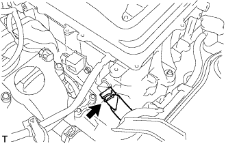
Loosen the bleeder plug shown in the illustration and connect a hose.
Add coolant from the reserve tank.
 |
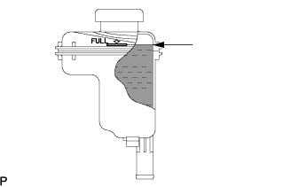
Add coolant until the level of coolant in the hose attached to the bleeder plug reaches the same level as the FULL line of the reserve tank.
When using the intelligent tester:
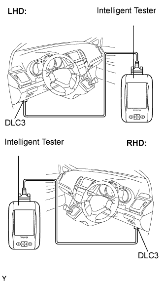 |
Connect the intelligent tester to the DLC3.
Turn the ignition switch to the ON position.
Select the inspection mode (Click here).
On the tester, enter the following menus: Powertrain / Hybrid Control / Active test / Water Pump.
Keep the coolant at the FULL level in the reserve tank to compensate for the drop in coolant level when the air bleeds.
When not using the intelligent tester:
Put the vehicle into the READY-on state. [*1]
Turn the ignition switch off and add coolant to the FULL level because the coolant level drops as the air bleeds. [*2]
Repeat steps [*1] and [*2] until air bleeding from the coolant system is completed.
When the air is completely bled from the coolant system, tighten the plug.
 |
Add coolant to the FULL mark of the reserve tank.
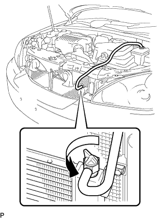
| 34. ADD ENGINE COOLANT |
Tighten the lower drain plug of the radiator.
Loosen the upper drain plug of the radiator.
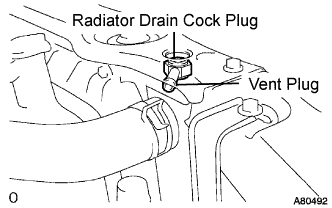 |
Install a vinyl tube to the vent plug located on the upper drain plug.
Fill the radiator with engine coolant until the vinyl tube is filled with the coolant.
Tighten the upper drain plug.
Install the radiator cap securely.
Fill the radiator reservoir tank with coolant.
Warm up the engine.
Stop the engine and wait until the coolant cools down.
Remove the radiator cap and check the coolant level inside the radiator.
If the coolant level is below the full level, perform the steps from (a) through (j) and repeat the operation until the coolant level stays the full level.
Recheck the coolant level inside the radiator reservoir tank. If it is below the full level, add the coolant.
| 35. CHECK HYBRID VEHICLE COOLANT LEAKS |
| 36. CHECK FOR ENGINE COOLANT LEAKS |
 |
Fill the radiator with coolant and attach a radiator cap tester.
Warm up the engine.
Using a radiator cap tester, increase the pressure inside the radiator to 118 kPa (1.2 kgf*cm, 17 psi), and check that the pressure does not drop.
If the pressure drops, check the hoses, radiator and water pump for leaks. If no external leaks are found, check the heater core, cylinder block and cylinder head.
| 37. PERFORM INITIALIZATION |
Some system need initialization when reconnecting the battery cable. (Click here)
