THERMOSTAT > REMOVAL |
| 1. PRECAUTION |
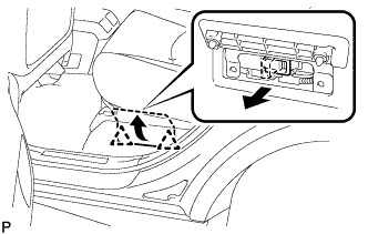
| 2. REMOVE ENGINE ROOM SIDE LH COVER |
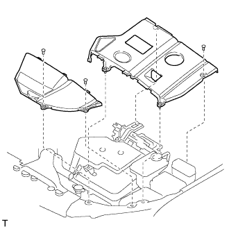 |
Using a clip remover, remove the engine room side cover.
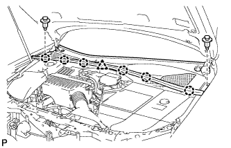
| 3. REMOVE ENGINE ROOM COVER SIDE |
 |
Remove the 5 clips and engine room cover side.
| 4. DRAIN HYBRIT VEHICLE COOLANT |
Remove the transaxle side reserve tank.
 |
Loosen the bleeder plug shown in the illustration and drain the coolant.
Close the bleeder plug.
 |
Remove the plug and gasket shown in the illustration and drain the coolant.
Install the plug with a new gasket.
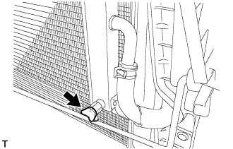
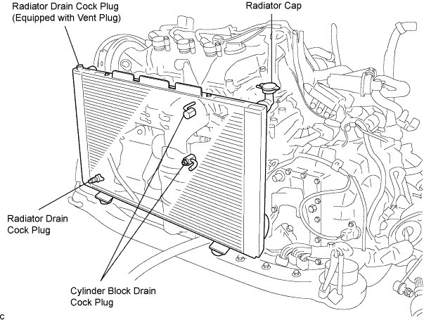
| 5. DRAIN ENGINE COOLANT |
Remove the radiator cap.
Drain the engine coolant by loosening the lower drain plug of the radiator and the cylinder block drain cock plugs.
Tighten the cylinder block drain cock plugs.
| 6. DISCONNECT BATTERY NEGATIVE CABLE |
| 7. REMOVE SERVICE PLUG GRIP |
 |
Remove the 2 clips, then open the battery service hole cover.
Wear insulation glove, and remove the service plug grip, after sliding up the lever of the service plug grip.
| 8. REMOVE FRONT WIPER AND BLADE ASSEMBLY ARM RH |
Remove the 2 nuts and the front wiper arm and blade assembly RH.
| 9. REMOVE FRONT WIPER AND BLADE ASSEMBLY ARM LH |
Remove the nut and the front wiper arm and blade assembly LH.
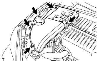
| 10. REMOVE COWL TOP VENTILATOR LOUVER SUB-ASSEMBLY |
 |
Remove the 2 clips.
Disengage the 6 claws and the clamp, and remove the cowl top ventilator louver sub-assembly.
| 11. REMOVE WINDSHIELD WIPER MOTOR ASSEMBLY |
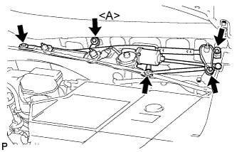 |
Disconnect the connector.
Remove the 5 bolts and the windshield wiper motor and link assembly.
| 12. REMOVE COWL TOP PANEL SUB-ASSEMBLY OUTER |
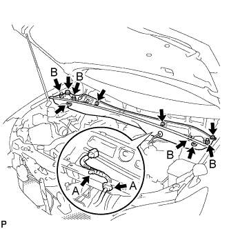 |
Separate the wire harness clamp and grommet (A).
Remove the 4 shock absorber nuts (B).
Remove the 4 bolts, 2 nuts and cowl top panel sub-assembly.
Install the 4 shock absorber nuts.
| 13. REMOVE COOL AIR INTAKE DUCT SEAL |
Remove the 4 clips and cool air intake duct seal.
| 14. REMOVE AIR CLEANER CAP W/INLET |
 |
Remove the 2 bolts, 4 clamps and air cleaner cap w/ inlet.
Remove the air cleaner filter element from the air cleaner case.
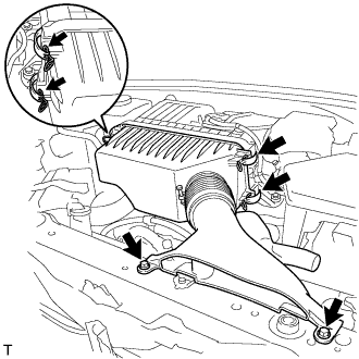
| 15. REMOVE AIR CLEANER W/RESONATOR |
 |
Separate the ventilation hose No.2.
 |
Disconnect the MAF meter connector.
Disconnect the 2 wire harness clamps from the air cleaner.
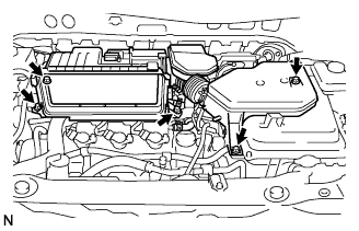 |
Remove the 5 bolts from the air cleaner case w/ resonator.
 |
Remove the hose clamp, and separate the air cleaner hose No.1.
Remove the air cleaner case w/ resonator.
| 16. REMOVE POWER STEERING ECU ASSEMBLY |
 |
Remove the bolt and ground cable terminal from the power steering ECU assembly.
 |
Release the locks of the 2 power steering ECU assembly connectors and disconnect the connectors.
 |
Separate the 2 wire harness clamps from the power steering ECU assembly.
 |
Remove the 2 bolts and the power steering ECU assembly.
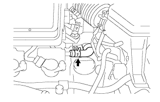
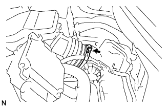
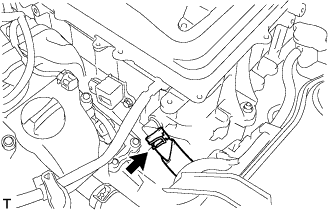
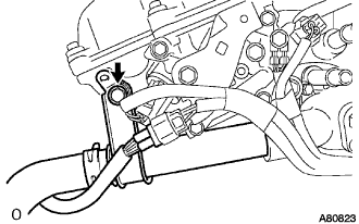
| 17. DISCONNECT CIRCUIT BREAKER SENSOR NO.1 |
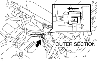 |
Move the outer section to the wire harness side as illustrated, then disconnect the circuit breaker sensor No.1.
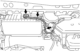
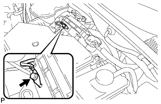
| 18. DISCONNECT ENGINE ROOM WIRE NO.2 |
 |
Remove the nut from the engine room wire No.2.
Release the claw, and disconnect the engine room wire No.2.
| 19. REMOVE INVERTER RESERVE TANK SUB-ASSEMBLY |
 |
Remove the 2 bolts and inverter reserve tank sub-assembly.
 |
Slide the 2 clamps, and disconnect the 2 water hoses from the inverter reserve tank sub-assembly.
| 20. DISCONNECT WATER HOSE |
 |
Slide the clamp, and disconnect the water hose from the w/ converter inverter assembly.
| 21. DISCONNECT POWER STEERING ECU BRACKET |
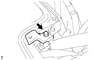 |
Remove the bolt, and disconnect the power steering ECU bracket.
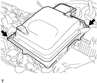
| 22. REMOVE INVERTER COVER |
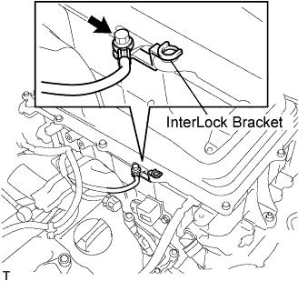 |
Remove the bolt and interlock bracket.
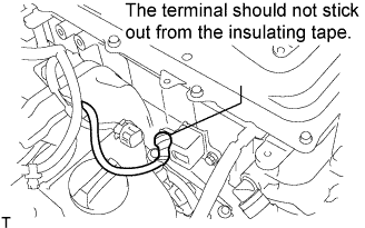 |
Insulate the removed terminal with insulating tape.
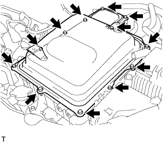 |
Remove the 12 bolts and inverter cover.
| 23. VERIFY VOLTAGE OF W/CONVERTER INVERTER ASSEMBLY IS 0 V |
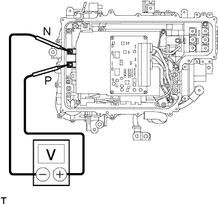 |
Using the voltmeter, measure the voltage between the terminals of the 2 phase connectors (N-P).
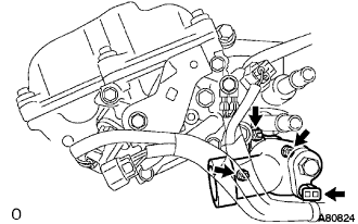
| 24. SEPARATE ENGINE WIRE NO.4 |
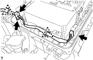 |
Remove the bolt, and disconnect the engine wire No.4 from the w/ converter inverter assembly.
Disconnect the connector, clamps and grommet, and separate the engine wire No.4 from the w/ converter inverter assembly.
| 25. DISCONNECT HIGHT VOLTAGE CABLE OF FRONT MOTER |
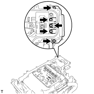 |
Remove the 5 bolts, and disconnect the high voltage cables of the Motor from the w/ converter inverter assembly.
 |
Remove the 5 bolts, and disconnect the high voltage cables of the Generator from the w/ converter inverter assembly.
| 26. DISCONNECT MG ECU CONNECTOR |
 |
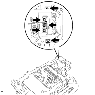
Disconnect the 2 connectors and grommets from the w/ converter inverter assembly.
| 27. DISCONNECT NO.3 WIRE FRAME |
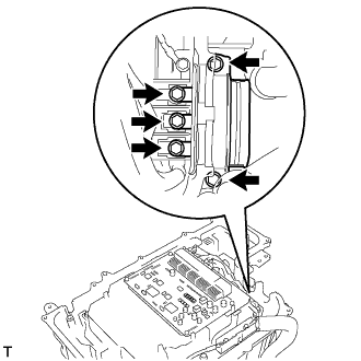 |
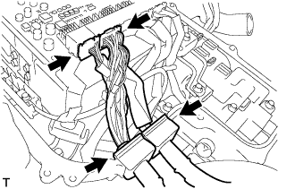
Remove the 5 bolts, and disconnect the No.3 wire frame (high voltage cables of the rear motor) from the w/ converter inverter assembly.
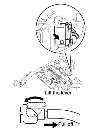 |
Remove the bolt and lift the lever to disconnect the No.3 wire frame from the w/ converter inverter assembly.
| 28. INSTALL INVERTER COVER |
 |
Temporarily install the inverter cover with the 2 bolts to prevent any foreign objects or waterdrops from entering the w/ converter inverter assembly.
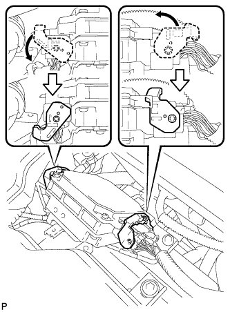
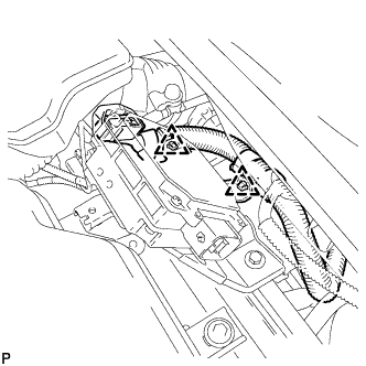
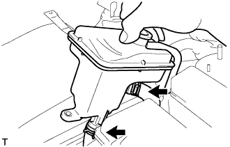
| 29. SEPARATE ENGINE ROOM RELAY BLOCK ASSEMBLY |
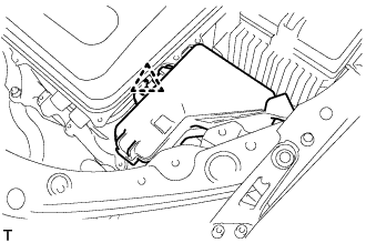 |
Disconnect the clamp, and release the engine room relay block assembly.
| 30. REMOVE INVERTER BRACKET NO.4 |
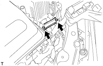 |
Remove the 2 bolts and inverter bracket No.4.
| 31. REMOVE W/CONVERTER INVERTER ASSEMBLY |
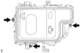 |
Remove the 2 nuts, bolt and w/ converter inverter assembly.
| 32. REMOVE WATER INLET PIPE |
 |
Remove the bolt and the water inlet pipe.
Remove the O-ring from the water inlet pipe.
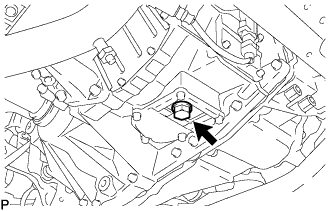
| 33. REMOVE WATER INLET |
 |
Disconnect the wire harness clamp.
Remove the 3 nuts and the water inlet.
| 34. REMOVE THERMOSTAT |
Remove the thermostat.
Remove the gasket from the thermostat.
