DTC P0AA6-526 Hybrid Battery Voltage System Isolation Fault |
DTC P0AA6-611 Hybrid Battery Voltage System Isolation Fault |
DTC P0AA6-612 Hybrid Battery Voltage System Isolation Fault |
DTC P0AA6-613 Hybrid Battery Voltage System Isolation Fault |
DTC P0AA6-614 Hybrid Battery Voltage System Isolation Fault |
DTC P0AA6-655 Hybrid Battery Voltage System Isolation Fault |
| DTC No. | INF Code | DTC Detection Condition | Trouble Area |
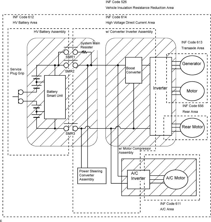
| P0AA6 | 526(*1) | Insulation resistance of the high-voltage circuit and the body is decreased. |
|
| ↑ | 611(*2) | Insulation resistance of the w/ motor compressor assembly is decreased. | w/ motor compressor assembly |
| ↑ | 612(*2) | Insulation resistance of the HV battery, battery smart unit, or HV relay assembly is decreased. |
|
| ↑ | 613(*2) | Insulation resistance of the HV transaxle assembly or w/ converter inverter assembly is decreased. |
|
| ↑ | 614(*2) | Insulation resistance of the w/ converter inverter assembly, HV relay assembly, power steering converter assembly, frame wire No.3 and w/ motor compressor are decreased. |
|
| ↑ | 655(*2) | Insulation resistance of the rear traction motor w/ transaxle assembly, frame wire, or w/ converter inverter assembly is decreased. |
|
| 1.READ OUTPUT DTC (HV) |
Connect the intelligent tester to the DLC3.
Turn the ignition switch to the ON position.
Select the following menu items: Powertrain / Hybrid Control / DTC.
Read output DTC. (Click here)
| Output DTC | Proceed to |
| P0AA6 only is output | A |
| P0AA6 and P0A1D (HV ECU malfunction) are output | B |
| P0AA6 and P0AA7 (Malfunction in the battery smart unit) are output | C |
| P0AA6 and P0A1D (HV ECU malfunction) are output | D |
|
| ||||
|
| ||||
|
| ||||
| A | |
| 2.READ OUTPUT INF CODE |
Connect the intelligent tester to the DLC3.
Turn the ignition switch to the ON position.
Select the following menu items: Powertrain / Hybrid Control / DTC / Freeze Frame Data / Inf Code.
Access the freeze frame data of DTC P0AA6 and read the INF code.
| Output INF | Proceed to |
| 526 (decrease in the insulation resistance of the high-voltage circuit) only is output | A |
| 526 and 611 (decrease in the insulation resistance of the air conditioner area) are output | Refer to the troubleshooting procedures for P0AA6-611 (Heater and air conditioner system) |
| 526 and 612 (decrease in the insulation resistance of the battery area) are output | B |
| 526 and 613 (decrease in the insulation resistance of the transaxle area) are output | C |
| 526 and 614 (decrease in the insulation resistance of the high-voltage DC area) are output | D |
| 526 and 655 (decrease in the insulation resistance of the rear area) are output | E |
|
| ||||
|
| ||||
|
| ||||
|
| ||||
| A | |
| 3.CHECK W/ MOTOR COMPRESSOR ASSEMBLY |
 |
Turn the ignition switch off and remove the service plug grip. (Click here)
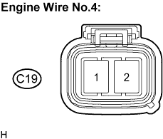
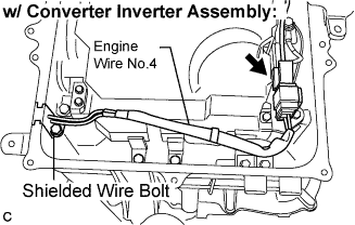
Disconnect the engine wire No.4 from the w/ motor compressor assembly.
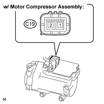 |
Using a megohmmeter, measure the insulation resistance according to the value(s) in the table below.
| Tester Connection | Specified Condition |
| (C19-1) - Body ground | 3 MΩ or higher |
| (C19-2) - Body ground | 3 MΩ or higher |
|
| ||||
| OK | |
| 4.CHECK HIGH VOLTAGE DIRECT CURRENT AREA, TRANSAXLE AREA, REAR MOTOR AREA |
Check that the service plug grip is removed.
 |
Using a megohmmeter, measure the insulation resistance according to the value(s) in the table below.
| Tester Connection | Specified Condition |
| (C19-1) - Body ground | 1 MΩ or higher |
| (C19-2) - Body ground | 1 MΩ or higher |
|
| ||||
| NG | |
| 5.CHECK ENGINE WIRE NO.4 |
 |
Check that the service plug grip is removed.
Remove the inverter cover. (Click here)
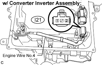
Disconnect the engine wire No.4 connector from the w/ converter inverter assembly.
 |
Using a megohmmeter, measure the insulation resistance according to the value(s) in the table below.
| Tester Connection | Specified Condition |
| (I21-1) - Body ground | 10 MΩ or higher |
| (I21-2) - Body ground | 10 MΩ or higher |
|
| ||||
| OK | |
| 6.CHECK HYBRID VEHICLE TRANSAXLE ASSEMBLY |
 |
Check that the service plug grip is removed.
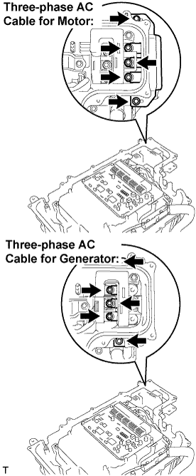
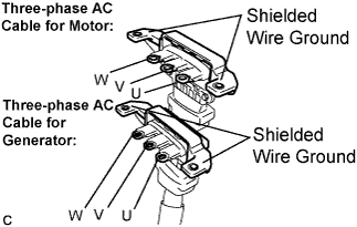
Disconnect the three-phase AC cables for Motor and Generator from the w/ converter inverter assembly.
 |
Using a megohmmeter, measure the insulation resistance according to the value(s) in the table below.
| Tester Connection | Specified Condition |
| Three-phase AC Cable for Motor U terminal - Body ground and shielded wire ground | 10 MΩ or higher |
| Three-phase AC Cable for Motor V terminal - Body ground and shielded wire ground | 10 MΩ or higher |
| Three-phase AC Cable for Motor W terminal - Body ground and shielded wire ground | 10 MΩ or higher |
| Three-phase AC Cable for Generator U terminal - Body ground and shielded wire ground | 10 MΩ or higher |
| Three-phase AC Cable for Generator V terminal - Body ground and shielded wire ground | 10 MΩ or higher |
| Three-phase AC Cable for Generator W terminal - Body ground and shielded wire ground | 10 MΩ or higher |
|
| ||||
| OK | |
| 7.CHECK REAR TRACTION MOTOR W/TRANSAXLE ASSEMBLY |
 |
Check that the service plug grip is removed.
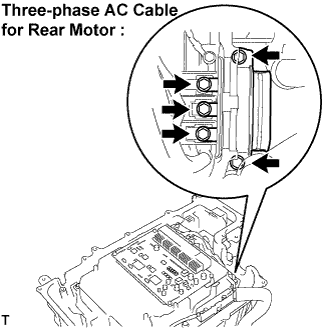
Disconnect the frame wire No.3 (three-phase AC cable for Rear Motor) from the w/ converter inverter assembly.
 |
Using a megohmmeter, measure the insulation resistance according to the value(s) in the table below.
| Tester Connection | Specified Condition |
| Three-phase AC Cable for Rear Motor U terminal - Body ground and shielded wire ground | 10 MΩ or higher |
| Three-phase AC Cable for Rear Motor V terminal - Body ground and shielded wire ground | 10 MΩ or higher |
| Three-phase AC Cable for Rear Motor W terminal - Body ground and shielded wire ground | 10 MΩ or higher |
|
| ||||
| OK | |
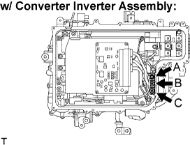
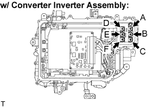
| 8.CHECK W/ CONVERTER INVERTER ASSEMBLY |
 |
Check that the service plug grip is removed.
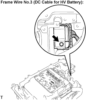
Disconnect the frame wire No.3 (DC cable for the HV battery) connector from the w/ converter inverter assembly.
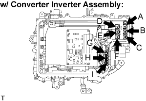 |
Using a megohmmeter, measure the insulation resistance according to the value(s) in the table below.
| Tester Connection | Specified Condition |
| A - Body ground | 1 MΩ or higher |
| B - Body ground | 1 MΩ or higher |
| C - Body ground | 1 MΩ or higher |
| D - Body ground | 1 MΩ or higher |
| E - Body ground | 1 MΩ or higher |
| F - Body ground | 1 MΩ or higher |
| G - Body ground | 1 MΩ or higher |
| H - Body ground | 1 MΩ or higher |
| I - Body ground | 1 MΩ or higher |
|
| ||||
| OK | |
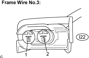
| 9.CHECK FRAME WIRE NO.3 |
 |
Check that the service plug grip is removed.
Remove the seat and HV battery cover. (Click here)
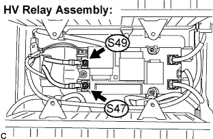
Disconnect the frame wire No.3 (DC cable for the w/ converter inverter assembly) from the HV relay assembly.
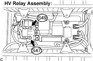 |
Using a megohmmeter, measure the insulation resistance according to the value(s) in the table below.
| Tester Connection | Specified Condition |
| (S47-1) - Body ground | 10 MΩ or higher |
| (S49-1) - Body ground | 10 MΩ or higher |
|
| ||||
| OK | |
| 10.CHECK HV RELAY ASSEMBLY |
 |
Check that the service plug grip is removed.
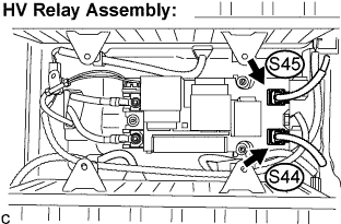
Disconnect the frame wire No.3 (connector for the power steering converter assembly) from the HV relay assembly.
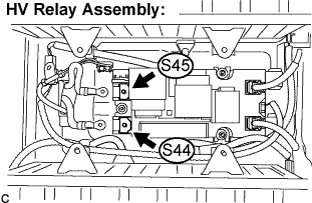 |
Using a megohmmeter, measure the insulation resistance according to the value(s) in the table below.
| Tester Connection | Specified Condition |
| (S45-1) - Body ground | 10 MΩ or higher |
| (S44-1) - Body ground | 10 MΩ or higher |
|
| ||||
| OK | |
| 11.CHECK POWER STEERING CONVERTER ASSEMBLY |
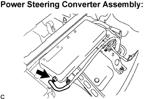 |
Check that the service plug grip is removed.
Disconnect the frame wire No.3 (connector for the HV battery) from the power steering converter assembly.
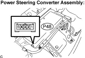 |
Using a megohmmeter, measure the insulation resistance according to the value(s) in the table below.
| Tester Connection | Specified Condition |
| (P48-1) - Body ground | 10 MΩ or higher |
| (P48-5) - Body ground | 10 MΩ or higher |
|
| ||||
| NG | ||
| ||
| 12.CHECK REAR TRACTION MOTOR W/TRANSAXLE ASSEMBLY |
|
Turn the ignition switch off and remove the service plug grip. (Click here)
Remove the inverter cover. (Click here)
Disconnect the frame wire No.3 (three-phase AC cable for the rear traction motor w/ transaxle assembly) from the w/ converter inverter assembly.
 |
Using a megohmmeter, measure the insulation resistance according to the value(s) in the table below.
| Tester Connection | Specified Condition |
| A - Body ground | 1 MΩ or higher |
| B - Body ground | 1 MΩ or higher |
| C - Body ground | 1 MΩ or higher |
|
| ||||
| OK | |
| 13.CHECK REAR TRACTION MOTOR W/TRANSAXLE ASSEMBLY |
 |
Check that the service plug grip is removed.
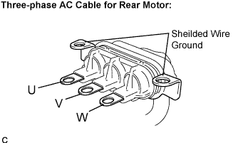
Disconnect the frame wire No.3 (three-phase AC cable for the rear traction motor w/ transaxle assembly) from the rear traction motor w/ transaxle assembly.
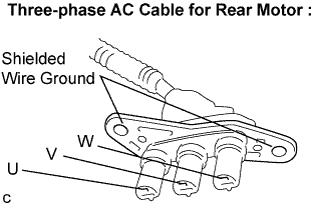 |
Using a megohmmeter, measure the insulation resistance according to the value(s) in the table below.
| Tester Connection | Specified Condition |
| U - Body ground and shielded wire ground | 10 MΩ or higher |
| V - Body ground and shielded wire ground | 10 MΩ or higher |
| W - Body ground and shielded wire ground | 10 MΩ or higher |
|
| ||||
| OK | ||
| ||
| 14.CHECK HV BATTERY AREA |
 |
Turn the ignition switch off and remove the service plug grip. (Click here)
Remove the seat and HV battery cover. (Click here)
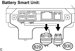
Disconnect the B29 and B30 connectors from the battery smart unit.
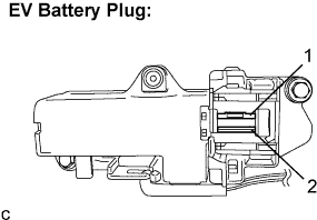 |
Using a megohmmeter, measure the insulation resistance according to the value(s) in the table below.
| Tester Connection | Specified Condition |
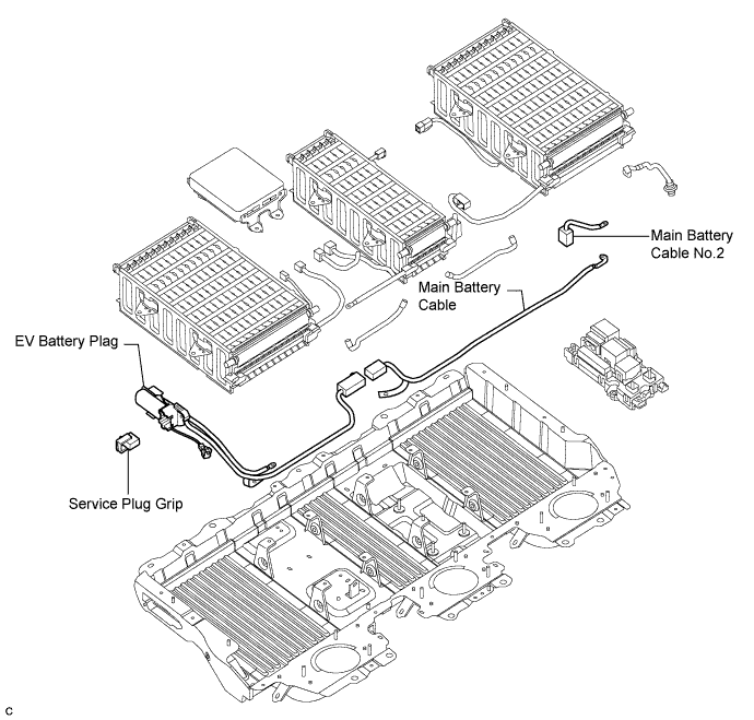
| EV battery plug 1 - Body ground | 10 MΩ or higher |
| EV battery plug 2 - Body ground | 10 MΩ or higher |
|
| ||||
| NG | |
| 15.CHECK HV RELAY ASSEMBLY |
Check that the service plug grip is removed.
Connect the B29 and B30 connectors to the battery smart unit.
 |
Disconnect the main battery cable No.2 (negative side and positive side) from the HV relay assembly.
|
Using a megohmmeter, measure the insulation resistance according to the value(s) in the table below.
| Tester Connection | Specified Condition |
| EV battery plug 1 - Body ground | 10 MΩ or higher |
| EV battery plug 2 - Body ground | 10 MΩ or higher |
|
| ||||
| NG | |
| 16.CHECK BATTERY CABLE AND SERVICE PLUG GRIP |
Check that the service plug grip is removed.
Remove the main battery cable No.2 (negative side) (Click here), and visually check that there is no scratch or peeling cover.
Remove the main battery cable (Click here), and visually check that there is no scratch or peeling cover.
Remove the EV battery plug (Click here), and visually check that there is no scratch or peeling cover.
Visually check that there are no scratches or peeling on the removed service plug grip.
|
| ||||
| OK | ||
| ||
| 17.CHECK HYBRID VEHICLE TRANSAXLE ASSEMBLY |
|
Turn the ignition switch off and remove the service plug grip. (Click here)
Remove the inverter cover. (Click here)
Disconnect the three-phase AC cables of the HV transaxle assembly (Motor and Generator) from the w/ converter inverter assembly.
 |
Using a megohmmeter, measure the insulation resistance according to the value(s) in the table below.
| Tester Connection | Specified Condition |
| A - Body ground | 1 MΩ or higher |
| B - Body ground | 1 MΩ or higher |
| C - Body ground | 1 MΩ or higher |
| D - Body ground | 1 MΩ or higher |
| E - Body ground | 1 MΩ or higher |
| F - Body ground | 1 MΩ or higher |
|
| ||||
| OK | ||
| ||
| 18.CHECK HIGH VOLTAGE DIRECT CURRENT AREA FOR INSULATION |
Turn the ignition switch off and remove the service plug grip. (Click here)
Remove the inverter cover. (Click here)
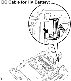 |
Disconnect the frame wire No.3 (DC cable for the HV battery) from the w/ converter inverter assembly.
 |
Using a megohmmeter, measure the insulation resistance according to the value(s) in the table below.
| Tester Connection | Specified Condition |
| (I22-1) - Body ground | 10 MΩ or higher |
| (I22-2) - Body ground | 10 MΩ or higher |
|
| ||||
| OK | |
| 19.CHECK W/ MOTOR COMPRESSOR ASSEMBLY |
|
Check that the service plug grip is removed.
Disconnect the engine wire No.4 from the w/ converter inverter assembly.
|
Using a megohmmeter, measure the insulation resistance according to the value(s) in the table below.
| Tester Connection | Specified Condition |
| (I21-1) - Body ground | 3 MΩ or higher |
| (I21-2) - Body ground | 3 MΩ or higher |
|
| ||||
| NG | |
| 20.CHECK W/ MOTOR COMPRESSOR ASSEMBLY |
|
Check that the service plug grip is removed.
Disconnect the engine wire No.4 from the w/ motor compressor assembly.
|
Using a megohmmeter, measure the insulation resistance according to the value(s) in the table below.
| Tester Connection | Specified Condition |
| (I21-1) - Body ground | 10 kΩ or higher |
| (I21-2) - Body ground | 10 kΩ or higher |
|
| ||||
| OK | ||
| ||
