DTC U0110-159 Lost Communication with Driver Motor Control Module |
DTC U0110-656 Lost Communication with Driver Motor Control Module |
DTC U0110-657 Lost Communication with Driver Motor Control Module |
| DTC No. | INF Code | DTC Detection Condition | Trouble Area |
| U0110 | 159 | Error in reception from w/ converter inverter assembly (MG ECU) via serial communication (out of communication standard) |
|
| U0110 | 656 | Error in reception from w/ converter inverter assembly (MG ECU) via serial communication (out of communication standard) |
|
| U0110 | 657 | Error in reception from w/ converter inverter assembly (MG ECU) via serial communication (no reception) |
|
| 1.INSPECT HYBRID VEHICLE CONTROL ECU |
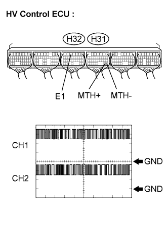 |
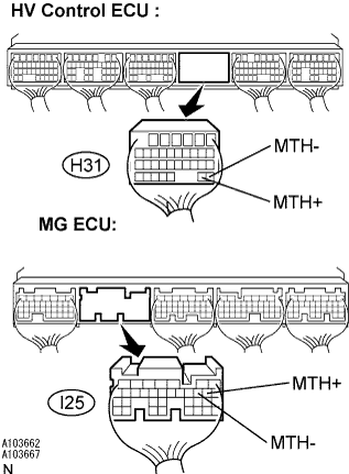
Connect the oscilloscope to the HV control ECU terminals specified in the table below and check the waveform.
| Item | Contents |
| Terminal | MTH+ (H31-28) - E1 (H32-5) MTH- (H31-27) - E1 (H32-5) |
| Equipment Setting | 1 V/DIV, 5 μs/DIV 1 V/DIV, 200 μs/DIV |
| Condition | READY-on state |
|
| ||||
| NG | |
| 2.INSPECT HYBRID VEHICLE CONTROL ECU |
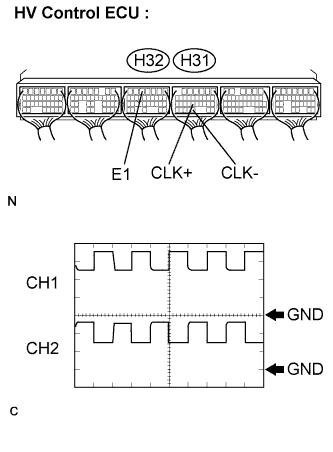 |
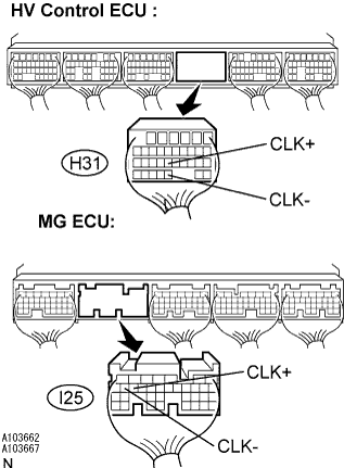
Connect the oscilloscope to the HV control ECU terminals specified in the table below and check the waveform.
| Item | Contents |
| Terminal | CLK+ (H31-22) - E1 (H32-5) CLK- (H31-29) - E1 (H32-5) |
| Equipment Setting | 1 V/DIV, 1 μs/DIV |
| Condition | READY-on state |
|
| ||||
| OK | |
| 3.INSPECT HYBRID VEHICLE CONTROL ECU |
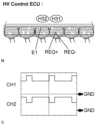 |
Set the intelligent tester to oscilloscope mode.
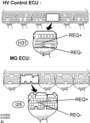
Connect the intelligent tester to the HV control ECU terminals specified in the table below and check the waveform.
| Item | Contents |
| Terminal | REQ+ (H31-23) - E1 (H32-5) REQ- (H31-30) - E1 (H32-5) |
| Equipment Setting | 1 V/DIV, 1 ms/DIV |
| Condition | READY ON |
|
| ||||
| OK | |
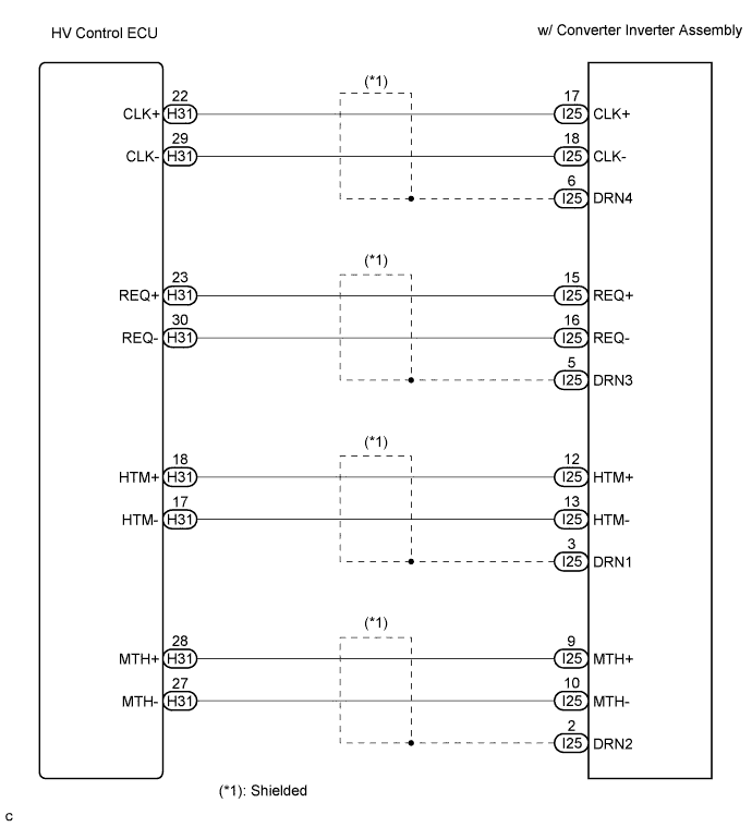
| 4.CHECK HARNESS AND CONNECTOR (HV CONTROL ECU - MG ECU) |
 |
Turn the ignition switch off and remove the service plug grip. (Click here)
Disconnect the H31 connector from the HV control ECU.
Remove the inverter cover. (Click here)
Disconnect the I25 connector from the MG ECU.
Measure the voltage according to the value(s) in the table below when the ignition switch is in the ON position.
| Tester Connection | Specified Condition |
| MTH+ (H31-28) - Body ground | Below 1 V |
| MTH- (H31-27) - Body ground | Below 1 V |
Turn the ignition switch off.
Measure the resistance according to the value(s) in the table below.
| Tester Connection | Specified Condition |
| MTH+ (H31-28) - MTH+ (I25-9) | Below 1 Ω |
| MTH- (H31-27) - MTH- (I25-10) | Below 1 Ω |
| Tester Connection | Specified Condition |
| MTH+ (H31-28) or MTH+ (I25-9) - Body ground | 10 kΩ or higher |
| MTH- (H31-27) or MTH- (I25-10) - Body ground | 10 kΩ or higher |
| HV control ECU or MG ECU - Body ground | 10 kΩ or higher |
|
| ||||
| OK | ||
| ||
| 5.CHECK HARNESS AND CONNECTOR (HV CONTROL ECU - MG ECU) |
 |
Turn the ignition switch off and remove the service plug grip. (Click here)
Disconnect the H31 connector from the HV control ECU.
Remove the inverter cover. (Click here)
Disconnect the I25 connector from the MG ECU.
Measure the voltage according to the value(s) in the table below when the ignition switch is in the ON position.
| Tester Connection | Specified Condition |
| CLK+ (H31-22) - Body ground | Below 1 V |
| CLK- (H31-29) - Body ground | Below 1 V |
Turn the ignition switch off.
Measure the resistance according to the value(s) in the table below.
| Tester Connection | Specified Condition |
| CLK+ (H31-22) - CLK+ (I25-17) | Below 1 Ω |
| CLK- (H31-29) - CLK- (I25-18) | Below 1 Ω |
| Tester Connection | Specified Condition |
| CLK+ (H31-22) or CLK+ (I25-17) - Body ground | 10 kΩ or higher |
| CLK- (H31-29) or CLK- (I25-18) - Body ground | 10 kΩ or higher |
|
| ||||
| OK | ||
| ||
| 6.CHECK HARNESS AND CONNECTOR (HV CONTROL ECU - MG ECU) |
 |
Turn the ignition switch off and remove the service plug grip. (Click here)
Disconnect the H31 connector from the HV control ECU.
Remove the inverter cover. (Click here)
Disconnect the I25 connector from the MG ECU.
Measure the voltage according to the value(s) in the table below when the ignition switch is in the ON position.
| Tester Connection | Specified Condition |
| REQ+ (H31-23) - Body ground | Below 1 V |
| REQ- (H31-30) - Body ground | Below 1 V |
Turn the ignition switch off.
Measure the resistance according to the value(s) in the table below.
| Tester Connection | Specified Condition |
| REQ+ (H31-23) - REQ+ (I25-15) | Below 1 Ω |
| REQ- (H31-30) - REQ- (I25-16) | Below 1 Ω |
| Tester Connection | Specified Condition |
| REQ+ (H31-23) or REQ+ (I25-15) - Body ground | 10 kΩ or higher |
| REQ+ (H31-23) or REQ+ (I25-15) - Body ground | 10 kΩ or higher |
|
| ||||
| OK | ||
| ||
