DTC    P0016    Crankshaft Position - Camshaft Position Correlation (Bank 1 Sensor A)

DTC    P0018    Crankshaft Position - Camshaft Position Correlation (Bank 2 Sensor A)

for Preparation Click here


DESCRIPTION

The crankshaft position sensor (NE signal) consists of a magnet, iron core and pickup coil.
The NE signal plate (crankshaft position sensor plate) has 34 teeth and is installed on the crankshaft. The NE signal sensor generates 34 signals for each engine revolution. This sensor monitors a plate (timing rotor) located on the crankshaft timing pulley and is used by the ECM to detect crankshaft angle and engine speed (RPM/NE). As the crankshaft timing pulley rotates through an engine revolution, this sensor communicates the rotation of the NE signal plate as a pulse signal to the ECM. Based on the signal, the ECM controls fuel injection time and ignition timing.

DTC No.
Detection Condition
Trouble Area
P0016
Deviation in crankshaft position sensor signal and VVT sensor 1 (bank 1) signal (2 trip detection logic)
  1. Mechanical system (Timing belt has jumped tooth or chain stretched)
  2. HV Control ECU
P0018
Deviation in crankshaft position sensor signal and VVT sensor 2 (bank 2) signal (2 trip detection logic)
  1. Mechanical system (Timing belt has jumped tooth or chain stretched)
  2. HV Control ECU

WIRING DIAGRAM

Refer to DTC P0335 (Click here).

INSPECTION PROCEDURE

HINT:
Read freeze frame data using the intelligent tester. The ECM records vehicle and driving condition information as freeze frame data the moment a DTC is stored. When troubleshooting, freeze frame data can help determine if the vehicle was moving or stationary, if the engine was warmed up or not, if the air-fuel ratio was lean or rich, and other data, from the time the malfunction occurred.

1.CHECK VALVE TIMING (CHECK FOR LOOSE AND A JUMPED TOOTH OF TIMING BELT)


    A109150
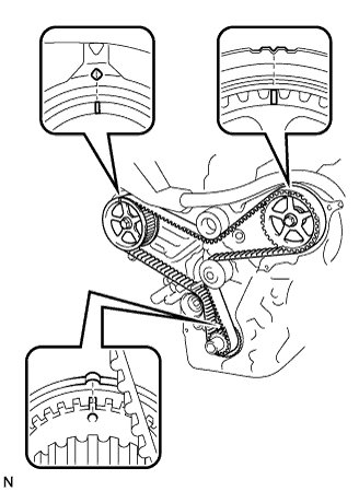
  1. Remove the cylinder head cover RH and LH.

  1. Turn the crankshaft pulley, and align its groove with the timing mark "0" of the timing belt cover.

  1. Check that the timing marks of the camshaft timing gears are aligned with the timing marks of the No.3 timing belt cover as shown in the illustration.
    If not, turn the crankshaft 1 revolution (360°), then align the marks as above.

    OK:
    Point marks on camshaft timing gears are aligned as shown in the illustration.

  1. Reinstall the cylinder head cover.


NG
ADJUST VALVE TIMING (REPAIR OR REPLACE TIMING BELT)
OK

REPLACE HV CONTROL ECU