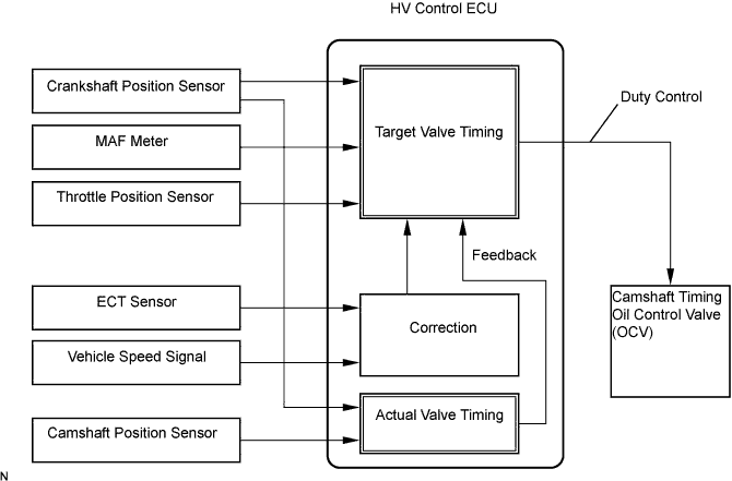
DTC P0010 Camshaft Position "A" Actuator Circuit (Bank 1) |
DTC P0020 Camshaft Position "A" Actuator Circuit (Bank 2) |
| DTC No. | DTC Detection Condition | Trouble Area |
| P0010 | Open or short OCV (bank 1) circuit (1 trip detection logic) |
|
| P0020 | Open or short OCV (bank 2) circuit (1 trip detection logic) |
|
| 1.PERFORM ACTIVE TEST BY CAMSHAFT TIMING OIL CONTROL VALVE ASSEMBLY (OCV) |
Connect the intelligent tester to the DLC3.
Turn the ignition switch ON and turn the tester ON.
Put the engine in inspection mode (Click here).
Warm up the engine.
On the tester, enter the following menus: Powertrain / Engine / Active Test / Active the VVT System (bank1) or Control the VVT System (bank2).
Check the engine speed while operating the Oil Control Valve (OCV) using the tester.
| Tester Operation | Specified Condition |
| OCV OFF | Normal engine speed |
| OCV ON | Engine idles roughly or stalls (soon after OCV switched from OFF to ON) |
|
| ||||
| NG | |
| 2.INSPECT CAMSHAFT TIMING OIL CONTROL VALVE ASSEMBLY (OCV FOR INTAKE CAMSHAFT) |
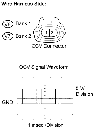 |
Disconnect the V7 or V8 OCV connector.
While idling, check the waveform between the terminals of the V7 or V8 OCV connector using an oscilloscope.
| Tester Connection | Specified Condition |
| V8-1 (+) - V8-2 (-) | Correct waveform is as shown |
| V7-1 (+) - V7-2 (-) | Correct waveform is as shown |
Reconnect the OCV connector.
|
| ||||
| NG | |
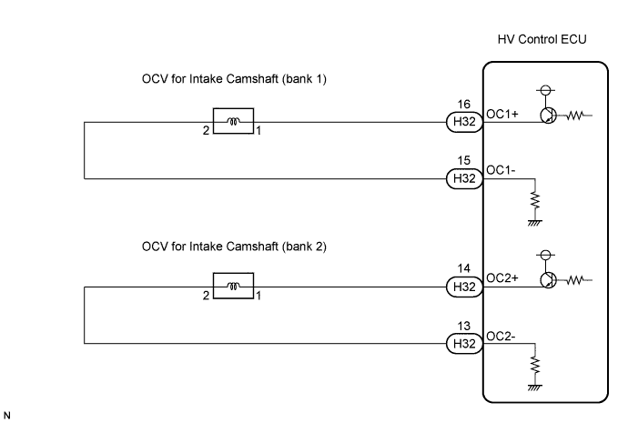
| 3.INSPECT HARNESS AND CONNECTOR (OCV - HV CONTROL ECU) |
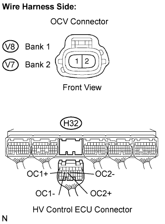 |
Disconnect the V7 or V8 OCV connector.
Disconnect the H32 HV Control ECU connector.
Check the resistance between the wire harness side connectors.
| Tester Connection | Specified Condition |
| OCV (V8-1) - OC1+ (H32-16) | Below 1 Ω |
| OCV (V8-2) - OC1- (H32-15) | Below 1 Ω |
| OCV (V7-1) - OC2+ (H32-14) | Below 1 Ω |
| OCV (V7-2) - OC2- (H32-13) | Below 1 Ω |
| Tester Connection | Specified Condition |
| OCV (V8-1) or OC1+ (H32-16) - Body ground | 10 kΩ or higher |
| OCV (V8-2) or OC1- (H32-15) - Body ground | 10 kΩ or higher |
| OCV (V7-1) or OC2+ (H32-14) - Body ground | 10 kΩ or higher |
| OCV (V7-2) or OC2- (H32-13) - Body ground | 10 kΩ or higher |
Reconnect the OCV connector.
Reconnect the ECM connector.
|
| ||||
| OK | ||
| ||
