DTC P0110 Intake Air Temperature Circuit Malfunction |
DTC P0112 Intake Air Temperature Circuit Low Input |
DTC P0113 Intake Air Temperature Circuit High Input |
| DTC No. | Proceed to | DTC Detection Condition | Trouble Area |
| P0110 | Step 1 | Open or short in Intake Air Temperature (IAT) sensor circuit for 0.5 seconds (1 trip detection logic) |
|
| P0112 | Step 4 | Short in Intake Air Temperature (IAT) sensor circuit for 0.5 seconds (1 trip detection logic) |
|
| P0113 | Step 2 | Open in Intake Air Temperature (IAT) sensor circuit for 0.5 seconds (1 trip detection logic) |
|
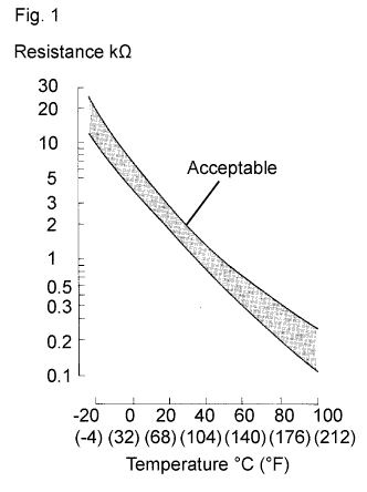
| Temperature Displayed | Malfunction |
| -40°C (-40°F) | Open circuit |
| 140°C (284°F) or higher | Short circuit |
| 1.READ VALUE USING INTELLIGENT TESTER (INTAKE AIR TEMPERATURE) |
Connect the intelligent tester to the DLC3.
Turn the ignition switch ON.
Turn the tester ON.
Enter the following menus: Powertrain / Engine / Data List / Intake Air.
Read the value displayed on the tester.
| Temperature Displayed | Proceed to |
| -40 °C (-40°F) | A |
| 140°C (284°F) or higher | B |
| Same as actual IAT | C |
|
| ||||
|
| ||||
| A | |
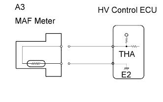
| 2.READ VALUE USING INTELLIGENT TESTER (CHECK FOR OPEN IN WIRE HARNESS) |
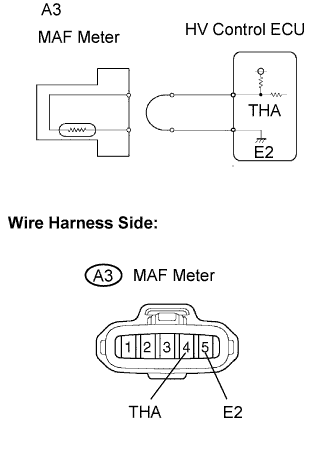 |
Disconnect the A3 Mass Air Flow (MAF) meter connector.
Connect terminals THA and E2 of the MAF meter wire harness side connector.
Connect the intelligent tester to the DLC3.
Turn the ignition switch ON.
Turn the tester ON.
Enter the following menus: Powertrain / Engine / Data List / Intake Air.
Read the value displayed on the tester.
Reconnect the MAF meter connector.
|
| ||||
| NG | |
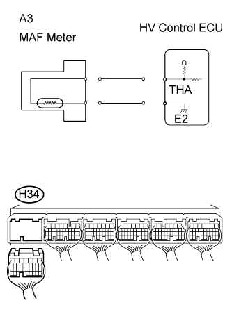
| 3.READ VALUE USING INTELLIGENT TESTER (CHECK FOR OPEN IN ECM (INCLUDED IN HV CONTROL ECU)) |
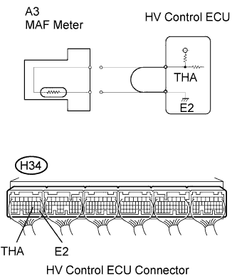 |
Disconnect the A3 MAF meter connector.
Connect terminals THA and E2 of the H34 HV Control ECU connector.
Connect the intelligent tester to the DLC3.
Turn the ignition switch ON.
Turn the tester ON.
Enter the following menus: Powertrain / Engine / Data List / Intake Air.
Read the value displayed on the tester.
Reconnect the MAF meter connector.
|
| ||||
| NG | ||
| ||
| 4.READ VALUE USING INTELLIGENT TESTER (CHECK FOR SHORT IN WIRE HARNESS) |
 |
Disconnect the A3 MAF meter connector.
Connect the intelligent tester to the DLC3.
Turn the ignition switch ON.
Turn the tester ON.
Enter the following menus: Powertrain / Engine / Data List / Intake Air.
Read the value displayed on the tester.
Reconnect the MAF meter connector.
|
| ||||
| NG | |
| 5.READ VALUE USING INTELLIGENT TESTER (CHECK FOR SHORT IN ECM (INCLUDED IN HV CONTROL ECU)) |
 |
Disconnect the H34 HV Control ECU connector.
Connect the intelligent tester to the DLC3.
Turn the ignition switch ON.
Turn the tester ON.
Enter the following menus: Powertrain / Engine / Data List/ Intake Air.
Read the value displayed on the tester.
Reconnect the HV Control ECU connector.
|
| ||||
| NG | ||
| ||
