DTC P0120 Throttle Pedal Position Sensor / Switch "A" Circuit Malfunction |
DTC P0122 Throttle / Pedal Position Sensor / Switch "A" Circuit Low Input |
DTC P0123 Throttle / Pedal Position Sensor / Switch "A" Circuit High Input |
DTC P0220 Throttle / Pedal Position Sensor / Switch "B" Circuit |
DTC P0222 Throttle / Pedal Position Sensor / Switch "B" Circuit Low Input |
DTC P0223 Throttle / Pedal Position Sensor / Switch "B" Circuit High Input |
DTC P2135 Throttle / Pedal Position Sensor / Switch "A" / "B" Voltage Correlation |
| DTC No. | DTC Detection Condition | Trouble Area |
| P0120 | Output voltage of VTA1 quickly fluctuates beyond lower and upper malfunction thresholds for 2 seconds (1 trip detection logic) |
|
| P0122 | Output voltage of VTA1 0.2 V or less for 2 seconds (1 trip detection logic) |
|
| P0123 | Output voltage of VTA1 4.535 V or more for 2 seconds (1 trip detection logic) |
|
| P0220 | Output voltage of VTA2 quickly fluctuates beyond lower and upper malfunction thresholds for 2 seconds (1 trip detection logic) |
|
| P0222 | Output voltage of VTA2 1.75 V or less for 2 seconds (1 trip detection logic) |
|
| P0223 | Output voltage of VTA2 4.535 V or more, and VTA1 between 0.2 V and 2.02 V, for 2 seconds (1 trip detection logic) |
|
| P2135 | Either condition (a) or (b) met (1 trip detection logic): (a) Difference between output voltages of VTA1 and VTA2 0.02 V or less for 0.5 seconds or more (b) Output voltage of VTA1 0.2 V or less, and VTA2 1.75 V or less, for 0.4 seconds or more |
|
| Tester Display | Accelerator Pedal Fully Released | Accelerator Pedal Fully Depressed |
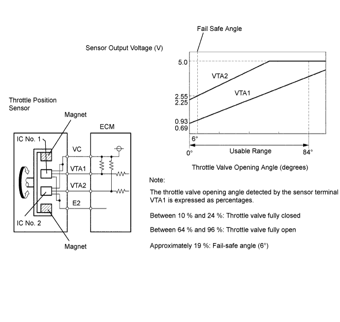
| THROTTLE POS | 10 to 24 % | 64 to 96 % |
| THROTTLE POS #2 | 2.1 to 3.1 V | 4.5 to 5.0 V |
| 1.READ VALUE USING INTELLIGENT TESTER (THROTTLE POS AND THROTTLE POS #2) |
Connect the intelligent tester to the DLC3.
Turn the ignition switch ON and turn the intelligent tester ON.
Enter the following menus: Powertrain / Engine / Data List / Throttle POS and Throttle POS #2.
Check the values displayed on the tester.
| TP#1 (VTA1) When AP Released | TP#2 (VTA2) When AP Released | TP#1 (VTA1) When AP Depressed | TP#2 (VTA2) When AP Depressed | Trouble Area | Proceed to |
| 0 % | Between 0 V and 0.2 V | 0 % | Between 0 V and 0.2 V | VC circuit open | A |
| 100 % | Between 4.5 V and 5.0 V | 100 % | Between 4.5 V and 5.0 V | E2 circuit open | A |
| 0 % or 100 % | Between 2.1 V and 3.1 V (Fail-safe) | 0 % or 100 % | Between 2.1 V and 3.1 V (Fail-safe) | VTA1 circuit open or ground short | A |
| Approx 19 % (Fail-safe) | Between 0 V and 0.2 V, or 4.5 V and 5.0 V | Between 10 % and 24 % (Fail-safe) | Between 0 V and 0.2 V, or 4.5 V and 5.0 V | VTA2 circuit open or ground short | A |
| Between 10 % and 24 % | Between 2.1 V and 3.1 V | Between 64 % and 96 % (Not fail-safe) | Between 4.5 V and 5.0 V (Not fail-safe) | TP sensor circuit normal | B |
|
| ||||
| A | |
| 2.CHECK HARNESS AND CONNECTOR (THROTTLE POSITION SENSOR - HV CONTROL ECU) |
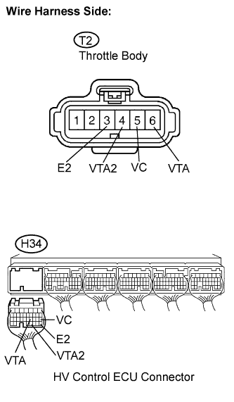 |
Disconnect the T2 throttle body connector.
Disconnect the H34 HV Control ECU connector.
Measure the resistance between the terminals of the throttle body and HV Control ECU.
| Tester Connection | Specified Condition |
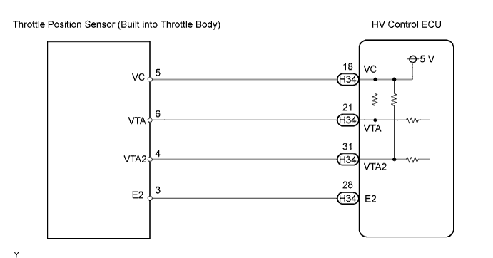
| VC (T2-5) - VC (H34-18) | Below 1 Ω |
| VTA (T2-6) - VTA (H34-21) | Below 1 Ω |
| VTA2 (T2-4) - VTA2 (H34-31) | Below 1 Ω |
| E2 (T2-3) - E2 (H34-28) | Below 1 Ω |
| Tester Connection | Specified Condition |
| VC (T2-5) or VC (H34-18) - Body ground | 10 kΩ or higher |
| VTA (T2-6) or VTA (H34-21) - Body ground | 10 kΩ or higher |
| VTA2 (T2-4) or VTA2 (H34-31) - Body ground | 10 kΩ or higher |
Reconnect the throttle body connector.
Reconnect the HV Control ECU connector.
|
| ||||
| OK | |
| 3.INSPECT HV CONTROL ECU (VC VOLTAGE) |
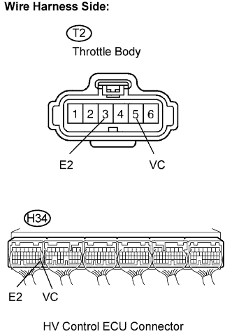 |
Disconnect the T2 throttle body connector.
Turn the ignition switch ON.
Measure the voltage between the terminals VC and E2 of the H34 HV Control ECU connector.
| Tester Connection | Specified Condition |
| VC (H34-18) - E2 (H34-28) | 4.5 to 5.0 V |
Reconnect the throttle body connector.
|
| ||||
| OK | |
| 4.REPLACE THROTTLE BODY ASSEMBLY |
| NEXT | |
| 5.CHECK WHETHER DTC OUTPUT RECURS (THROTTLE POSITION SENSOR DTCS) |
Connect the intelligent tester to the DLC3.
Turn the ignition switch ON and turn the tester ON.
Clear DTCs (Click here).
Put the engine in inspection mode (Click here).
Start the engine.
Allow the engine to idle for 15 seconds or more.
Enter the following menus: Powertrain / Engine / DTC.
Read DTCs.
| Display (DTC Output) | Proceed to |
| P0120, P0122, P0123, P0220, P0223, and/or P2135 | A |
| No output | B |
|
| ||||
| A | ||
| ||
