DTC P0037 Oxygen Sensor Heater Control Circuit Low (Bank 1 Sensor 2) |
DTC P0038 Oxygen Sensor Heater Control Circuit High (Bank 1 Sensor 2) |
DTC P0057 Oxygen Sensor Heater Control Circuit Low (Bank 2 Sensor 2) |
DTC P0058 Oxygen Sensor Heater Control Circuit High (Bank 2 Sensor 2) |
| DTC No. | DTC Detection Condition | Trouble Area |
| P0037 P0057 | Heated Oxygen (HO2) sensor heater current less than 0.25 A (1 trip detection logic) |
|
| P0038 P0058 | Heated Oxygen (HO2) sensor heater current more than 2 A (1 trip detection logic) |
|
| 1.INSPECT HEATED OXYGEN SENSOR (HEATER RESISTANCE) |
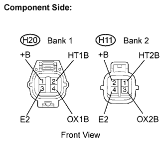 |
Disconnect the H20 or H11 heated oxygen (HO2) sensor connectors.
Measure the resistance between the terminals of the HO2 sensor connector.
| Tester Connection | Specified Condition |
| HT1B (2) - +B (1) | 11 to 16 Ω at 20°C (68°F) |
| HT1B (2) - E2 (3) | 10 kΩ or higher |
| Tester Connection | Specified Condition |
| HT2B (1) - +B (2) | 11 to 16 Ω at 20°C (68°F) |
| HT2B (1) - E2 (4) | 10 kΩ or higher |
Reconnect the HO2 sensor connector.
|
| ||||
| OK | |
| 2.INSPECT IGCT RELAY |
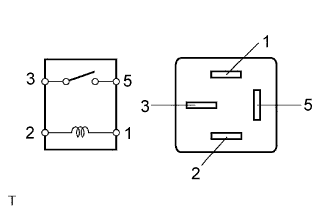 |
Remove the IGCT relay from the engine room R/B.
Inspect the IGCT relay.
| Terminal Connection | Specified Condition |
| 3 - 5 | 10 kΩ or higher |
| 3 - 5 | Below 1 Ω (When battery voltage applied to terminals 1 and 2) |
Reinstall the IGCT relay.
|
| ||||
| OK | |
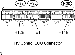
| 3.INSPECT HV CONTROL ECU (HT1B OR HT2B VOLTAGE) |
 |
Turn the ignition switch ON.
Measure the voltage between the terminals of the H29, H32 and H33 HV Control ECU connectors.
| Terminal Connection | Specified Condition |
| HT1B (H29-21) - E1 (H32-5) | 9 to 14 V |
| HT2B (H33-33) - E1 (H32-5) | 9 to 14 V |
|
| ||||
| NG | |
| 4.CHECK HARNESS AND CONNECTOR (HEATED OXYGEN SENSOR - IGCT NO.4 FUSE) |
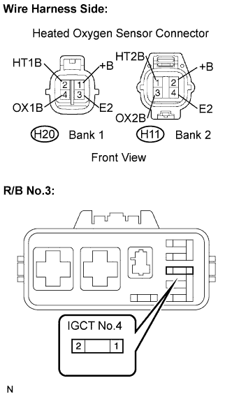 |
Check the harness and connector between the HO2 sensor and IGCT fuse.
Disconnect the H11 or H20 HO2 sensor connector.
Remove the IGCT No.4 fuse from the R/B No.3.
Measure the resistance between the terminals of the HO2 sensor and IGCT No.4 fuse.
| Terminal Connection | Specified Condition |
| +B (H20-1) - IGCT No.4 fuse (2) | Below 1 Ω |
| +B (H11-2) - IGCT No.4 fuse (2) | Below 1 Ω |
| Terminal Connection | Specified Condition |
| +B (H20-1) or IGCT No.4 fuse (2) - Body ground | 10 kΩ or higher |
| +B (H11-2) or IGCT No.4 fuse (2) - Body ground | 10 kΩ or higher |
Reconnect the HO2 sensor connector.
Reconnect the IGCT No.4 fuse.
|
| ||||
| OK | |
| 5.CHECK HARNESS AND CONNECTOR (HEATED OXYGEN SENSOR - HV CONTROL ECU) |
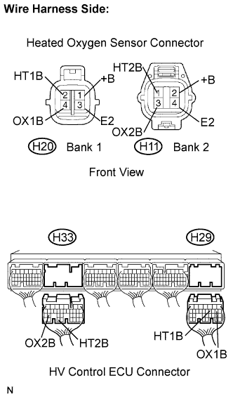 |
Check the harness and connector between the HV Control ECU and HO2 sensor.
Disconnect the H20 or H11 HO2 sensor connector.
Remove the H29 and H33 HV Control ECU connector.
Measure the resistance between the terminals of the HO2 sensor and HV Control ECU.
| Terminal Connection | Specified Condition |
| HT1B (H20-1) - HT1B (H29-21) | Below 1 Ω |
| HT2B (H11-2) - HT2B (H33-33) | Below 1 Ω |
| HT1B (H20-1) or HT1B (H29-21) - Body ground | 10 kΩ or higher |
| HT2B (H11-2) or HT2B (H33-33) - Body ground | 10 kΩ or higher |
Reconnect the HO2 sensor connector.
Reconnect the HV Control ECU connector.
|
| ||||
| OK | ||
| ||
