DTC P2118 Throttle Actuator Control Motor Current Range / Performance |
| DTC No. | DTC Detection Condition | Trouble Area |
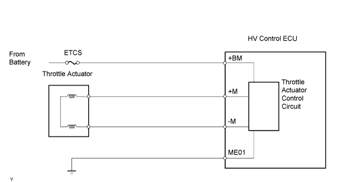
| P2118 | Open in ETCS power source (+BM) circuit (1 trip detection logic) |
|
| 1.CHECK FUSE (ETCS FUSE) |
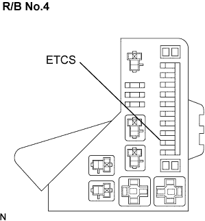 |
Remove the ETCS fuse from the engine R/B No.4.
Check the ETCS fuse resistance.
Reinstall the ETCS fuse.
|
| ||||
| OK | |
| 2.INSPECT HV CONTROL ECU (+BM VOLTAGE) |
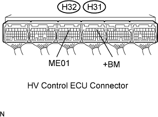 |
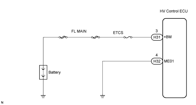
Measure the voltage between the terminals of the H32 and H31 HV Control ECU connectors.
| Tester Connection | Specified Condition |
| +BM (H31-3) - ME01 (H32-4) | 9 to 14 V |
|
| ||||
| NG | |
| 3.CHECK HARNESS AND CONNECTOR (HV CONTROL ECU - ETCS FUSE, ETCS FUSE - BATTERY) |
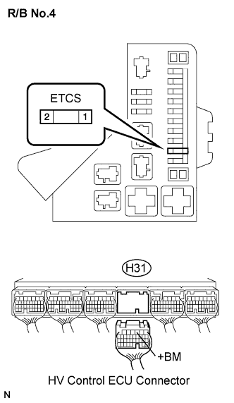 |
Check the harness and connector between the ETCS fuse and HV Control ECU.
Remove the ETCS fuse from the engine R/B No.4.
Disconnect the H31 HV Control ECU connector.
Measure the resistance between the terminal of the ETCS fuse and HV Control ECU.
| Tester Connection | Specified Condition |
| ETCS fuse (2) - +BM (H31-3) | Below 1 Ω |
| Tester Connection | Specified Condition |
| ETCS fuse (2) or +BM (H31-3) - Body ground | 10 kΩ or higher |
Reinstall the ETCS fuse.
Reconnect the HV Control ECU connector.
Check the harness and connector between the ETCS fuse and positive battery cable.
Remove the ETCS fuse from the engine R/B No.4.
Disconnect the positive battery cable.
Measure the resistance between the ETCS fuse and battery.
| Tester Connection | Specified Condition |
| Positive battery cable - ETCS fuse (1) | Below 1 Ω |
| Tester Connection | Specified Condition |
| Positive battery cable or ETCS fuse (1) - Body ground | 10 kΩ or higher |
Reinstall the ETCS fuse.
Reconnect the positive battery cable.
|
| ||||
| OK | ||
| ||
