WIPER AND WASHER SYSTEM > TERMINALS OF ECU |
| WINDSHIELD WIPER RELAY ASSEMBLY |
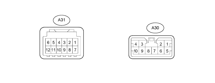
| Symbols (Terminals No.) | Wiring Color | Terminal Description | Condition | Specified Condition |
| MPX1(A31-1) - E(A31-12) | BR - W-B | Multiplex communication signal | Ignition switch OFF Ignition switch ON | Below 1 V Signal Waveform |
| VR1(A31-3) - E(A31-12) | R - W-B | Wiper switch (Rain sensor adjust switch signal) | Ignition switch OFF Ignition switch ON | Below 1 V 4.5 to 5.5 V |
| FWAS (A31-6) - E (A31-12) | W - W-B | Front washer motor (operate signal) | Front washer switch OFF Front washer switch ON | 10 to 14 V Below 1 V |
| AUTO (A31-7) - E (A31-12) | V- W-B | Wiper switch (AUTO signal) | Front wiper switch is in any position other than AUTO Front wiper switch is AUTO | 10 to 14 V Below 1 V |
| +B (A31-8) - E (A31-12) | SB - W-B | Battery (+B circuit) | Always | 10 to 14 V |
| VR2 (A31-9) - E (A31-12) | G - W-B | Wiper switch (Rain sensor adjust switch signal ground) | Always | 0 to 5.5 V |
| E (A31- 12) - Body ground | W-B - Body ground | Body ground | Always | Below 1 V |
| +1 (A30-1) - E (A31-12) | V - W-B | Front wiper motor (LO operation signal) | Front wiper motor is OFF Front wiper motor is in LO operation | Below 1 V 10 to 14 V |
| +2 (A30-2) - E (A31-12) | P - W-B | Front wiper motor (HI operation signal) | Front wiper motor is OFF Front wiper motor is in HI operation | Below 1 V 10 to 14 V |
| +SM (A30-5) - E (A31-12) | R - W-B | Front wiper motor (Operation signal) | Front wiper motor is OFF Front wiper motor is in LO or HI operation | Below 1 V 10 to 14 V |
| 2S (A30-6) - E (A31-12) | GR - W-B | Wiper switch (HI signal) | Front wiper switch is in any position other than HI Front wiper switch is HI | 10 to 14 V Below 1 V |
| 1S (A30-7) - E (A31-12) | SB - W-B | Wiper switch (LO signal) | Front wiper switch is in any position other than LO Front wiper switch is LO | 10 to 14 V Below 1 V |
| ES (A30-8) - E (A31-12) | L - W-B | wiper switch (Signal source) | Front wiper switch is OFF or AUTO | Below 1V |
| WIG (A30-10) - E (A31-12) | Y - W-B | Battery (Power source circuit) | Ignition switch OFF Ignition switch ON | Below 1V 10 to 14 V |
| HEADLIGHT CLEANER CONTROL RELAY |
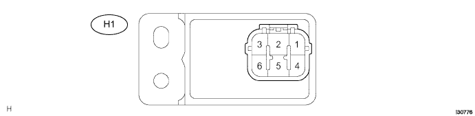
| Symbols (Terminal No.) | Wiring Color | Terminal Description | Condition | Specified Condition |
| IG (H1-1) - E (H1-5) | P - W-B | Battery (Power source circuit) | Ignition switch is OFF Ignition switch is ON | Below 1V 10 to 14 V |
| PB (H1-2) - E (H1-5) | B - W-B | Headlight cleaner motor (operation signal) | Headlight cleaner motor is stopped Headlight cleaner motor is operated | 10 to 14 V Below 1V |
| HDLO (H1-3) - E (H1-5) | L - W-B | Multiplex network body ECU (Cancel signal) | Daytime running light is stopped Daytime running light is operated | Below 1V 10 to 14 V |
| H (H1-4) - E (H1-5) | W - W-B (*1) R - W-B (*2) | Headlight cleaner switch (Operate signal) | Headlight cleaner switch is OFF Headlight switch is HEAD and headlight cleaner switch is ON | Below 1V 10 to 14 V |
| E (H1-5) - Body ground | W-B - Body ground | Body ground | Always | Below 1V |
| FRWA (H1-6) - E (H1-5) | V - W-B | Front washer motor (Operate signal) | Front washer switch is OFF Front washer switch is ON | 10 to 14 V Below 1V |
