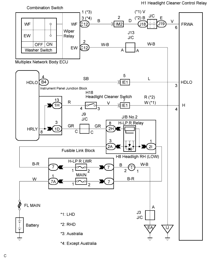
WIPER AND WASHER SYSTEM > Headlight Cleaner Switch Circuit |
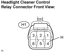
| 1.INSPECT HEADLIGHT CLEANER CONTROL RELAY |
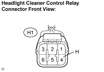 |
Disconnect the connector from the headlight cleaner control relay.
Measure the voltage according to the value(s) in the table below.
| Tester Connection | Condition | Specified Condition |
| H - Body ground | light control switch HEAD, headlight cleaner switch OFF → ON | Below 1 V → 10 to 14 V |
|
| ||||
| OK | |
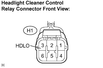
| 2.INSPECT HEADLIGHT CLEANER CONTROL RELAY |
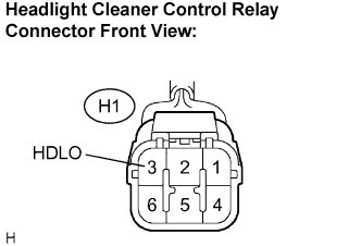 |
Measure the voltage according to the value(s) in the table below.
| Tester Connection | Condition | Specified Condition |
| HDLO - Body ground | Engine idling, parking brake released, Light control switch OFF and shift in any position other than P position. | 10 to 14 V |
|
| ||||
| OK | |
| 3.INSPECT HEADLIGHT CLEANER CONTROL RELAY |
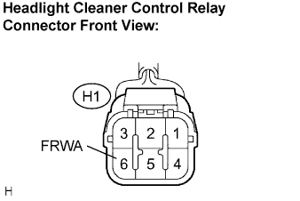 |
Measure the resistance according to the value(s) in the table below.
| Tester Connection | Condition | Specified Condition |
| FRWA - Body ground | Front washer switch OFF → ON | 10 kΩ or higher → Below 1 Ω |
|
| ||||
| OK | ||
| ||
| 4.INSPECT HEADLIGHT CLEANER SWITCH ASSEMBLY |
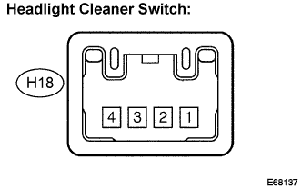 |
Disconnect the connector from the headlight cleaner switch.
Measure the resistance according to the value(s) in the table below.
| Tester Connection | Condition | Specified Condition |
| 4 - 3 | Headlight cleaner switch not pushed → pushed | 10 kΩ or higher → Below 1 Ω |
|
| ||||
| OK | |
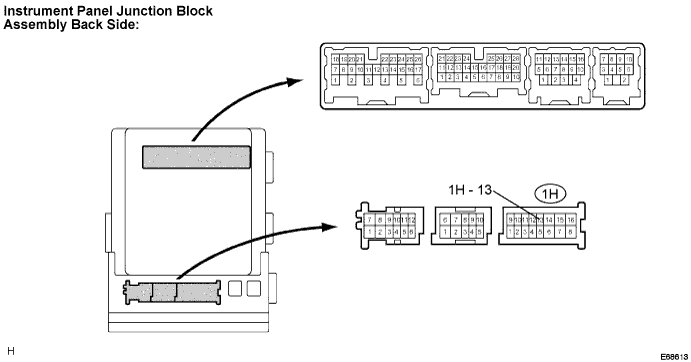
| 5.CHECK HARNESS AND CONNECTOR (HEADLIGHT CLEANER CONTROL RELAY - INSTRUMENT PANEL J/B)) |
 |
Disconnect the connector from the headlight cleaner control relay and instrument panel J/B.
Measure the resistance according to the value(s) in the table below.
| Tester Connection | Condition | Specified Condition |
| H - 1H-13 | Headlight cleaner switch not pushed → pushed | 10 kΩ or higher → Below 1 Ω |
| H - Body ground | Always | 10 kΩ or higher |
|
| ||||
| OK | ||
| ||
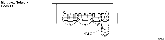
| 6.CHECK HARNESS AND CONNECTOR (HEADLIGHT CLEANER CONTROL RELAY - BODY ECU) |
 |
Disconnect the connector from the headlight cleaner and multiplex network body ECU.
Measure the resistance according to the value(s) in the table below.
| Tester Connection | Condition | Specified Condition |
| HDLO - HDLO | Always | Below 1 Ω |
| HDLO - Body ground | Always | 10 kΩ or higher |
|
| ||||
| OK | ||
| ||
| 7.INSPECT WINDSHIELD WIPER SWITCH ASSEMBLY |
Inspect the windshield wiper switch assembly (Click here).
|
| ||||
| OK | ||
| ||
