WIPER AND WASHER SYSTEM > Rain Sensor Circuit |
| 1.INSPECT FUSE |
Inspect the AM1, ECU-IG No.1 and INP-J/B fuses.
Measure the resistance between each terminals.
|
| ||||
| OK | |
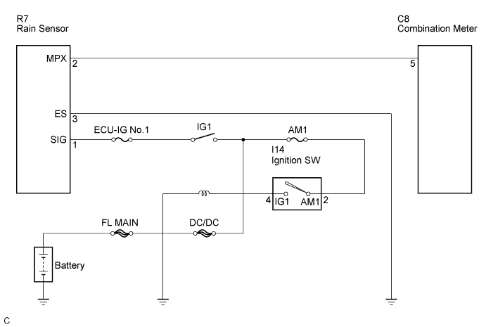
| 2.CHECK HARNESS AND CONNECTOR (RAIN SENSOR - BODY GROUND) |
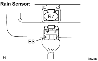 |
Disconnect the connector from the rain sensor.
Measure the resistance according to the value(s) in the table below.
| Tester Connection | Condition | Specified Condition |
| ES - Body ground | Always | Below 1 Ω |
|
| ||||
| OK | |
| 3.INSPECT RAIN SENSOR (RAIN SENSOR - OVERHEAD JUNCTION BLOCK) |
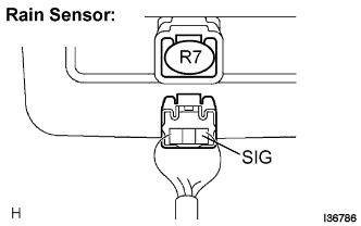 |
Disconnect the connector from the rain sensor.
Measure the voltage according to the value(s) in the table below.
| Tester Connection | Condition | Specified Condition |
| SIG - Body ground | Ignition switch OFF → ON | Below 1 V → 10 to 14 V |
|
| ||||
| OK | ||
| ||
