HYBRID VEHICLE TRANSAXLE ASSEMBLY > INSTALLATION |
| 1. INSTALL HYBRID VEHICLE TRANSAXLE ASSEMBLY |
Make sure that the knock pins are installed on the engine.
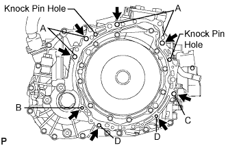 |
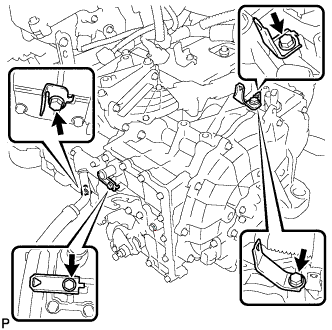
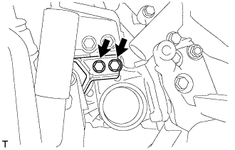
Install the hybrid vehicle transaxle and the 8 bolts shown in the illustration to the engine.
| Bolt | Installation direction | Diameter | Bolt length |
| A | From transaxle to engine | 12 mm (0.47 in.) | 55 mm (2.17 in.) |
| B | From engine to transaxle | 10 mm (0.39 in.) | 55 mm (2.17 in.) |
| C | From transaxle to engine | 12 mm (0.47 in.) | 55 mm (2.17 in.) |
| D | From engine to transaxle | 10 mm (0.39 in.) | 33 mm (1.30 in.) |
| 2. INSTALL TRANSMISSION CONTROL CABLE BRACKET NO.1 |
Install the control cable bracket No.1 and 2 new bolts.
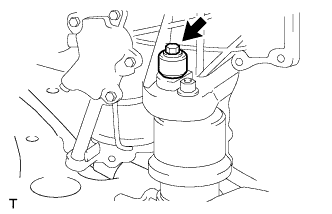
| 3. INSTALL OIL COOLER INLET TUBE SUB-ASSEMBLY |
Install the tube support bracket with the bolt.
Using SST and a wrench, tighten the new oil cooler inlet tube.
| 4. INSTALL OIL COOLER OUTLET TUBE SUB-ASSEMBLY |
Using SST and a wrench, tighten the new oil cooler outlet tube.
Install the oil cooler tube clamp with the bolt.
| 5. INSTALL ENGINE MOUNTING BRACKET FRONT |
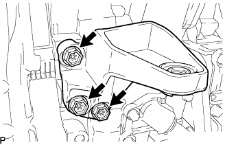 |
Install the engine mounting bracket front with the 3 bolts.
| 6. INSTALL WATER HOSE |
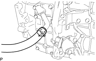 |
Install the water hose with the clamp.
| 7. INSTALL AUTOMATIC TRANSMISSION CASE COVER |
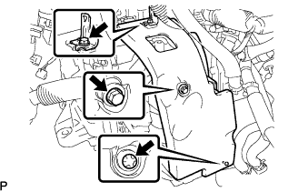 |
Install the case cover with the bolt and clip.
Install the wire harness bracket with the bolt.
| 8. CONNECT ENGINE WIRE |
 |
Install the 4 wire harness brackets with the bolts.
Connect the connector.
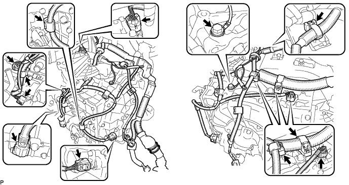
Connect the wire harnesses to the wire harness clamp.
Install the ground wire with the bolt.
| 9. INSTALL FLYWHEEL HOUSING UNDER COVER |
 |
Install the flywheel housing under cover with the 2 bolts.
| 10. INSTALL FRONT DRIVE SHAFT ASSEMBLY LH |
Install a new drive shaft hole snap ring.
Coat the spline of the inboard joint shaft assembly with ATF.
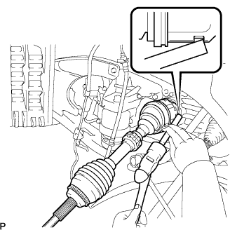 |
Align the shaft splines and install the drive shaft assembly with a brass bar and a hammer.
| 11. INSTALL FRONT DRIVE SHAFT ASSEMBLY RH |
Coat the spline of the inboard joint shaft assembly with ATF.
Align the shaft splines and install the drive shaft assembly.
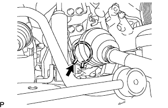 |
Using pliers, install a new bearing bracket hole snap ring.
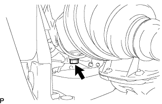 |
Install a new bolt to the drive shaft bearing bracket.
| 12. INSTALL FRONT FRAME ASSEMBLY |
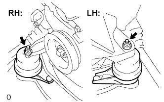 |
Install the engine mounting insulators RH and LH with the 2 nuts.
 |
Install the engine mounting insulator FR with the nut.
 |
Install the engine mounting insulator RR with the 2 bolts.
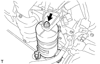
| 13. INSTALL HV TRANSAXLE MASS DAMPER |
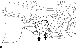
 |
Install the bolt and transaxle mass damper.
| 14. INSTALL MANIFOLD STAY |
Temporarily install the manifold stay to the exhaust manifold and transaxle.
Fully tighten the 2 bolts.
| 15. INSTALL ENGINE ASSEMBLY WITH TRANSAXLE |
