HYBRID TRANSAXLE OIL SEAL > INSTALLATION |
| 1. INSTALL HYBRID TRANSAXLE OIL SEAL |
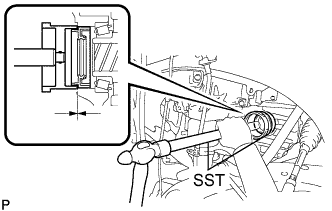 |
Install the oil seal LH side.
Using SST and a hammer, tap in a new oil seal until its surface is flush with the case edge.
Coat the lip of the oil seal with MP grease.
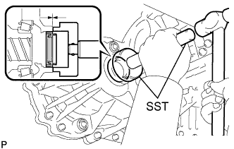 |
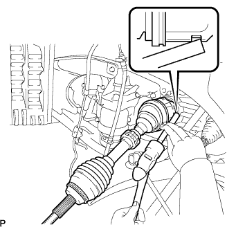
Install the oil seal RH side.
Using SST and a hammer, tap in a new oil seal until its surface is flush with the case edge.
Coat the lip of the oil seal with MP grease.
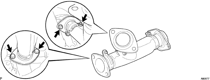
| 2. INSTALL EXHAUST PIPE SUB-ASSEMBLY FRONT NO.3 |
Install 2 new gaskets and the exhaust pipe front No.3 with the 2 bolts and 2 new nuts.
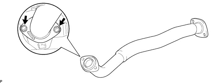
| 3. INSTALL EXHAUST PIPE ASSEMBLY FRONT |
Install the exhaust pipe front and a new gasket with 2 new nuts.
| 4. INSTALL FRONT DRIVE SHAFT ASSEMBLY LH |
Install a new drive shaft hole snap ring.
Coat the spline of the inboard joint shaft assembly with ATF.
 |
Align the shaft splines and install the drive shaft assembly with a brass bar and a hammer.
| 5. INSTALL FRONT DRIVE SHAFT ASSEMBLY RH |
Coat the spline of the inboard joint shaft assembly with ATF.
Align the shaft splines and install the drive shaft assembly.
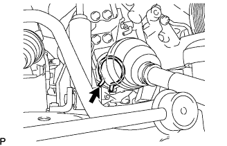 |
Using pliers, install a new bearing bracket hole snap ring.
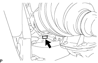 |
Install a new bolt to the drive shaft bearing bracket.
| 6. INSTALL FRONT SHOCK ABSORBER WITH COIL SPRING |
Install the front shock absorber with coil spring to the front axle assembly and insert the 2 bolts from the front side of the vehicle.
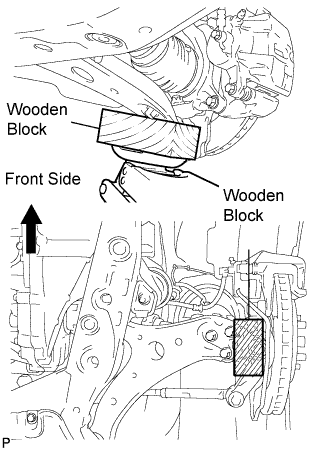 |
Slowly jack up the vehicle using a wooden block and install the front shock absorber with coil spring (upper side) to the vehicle.
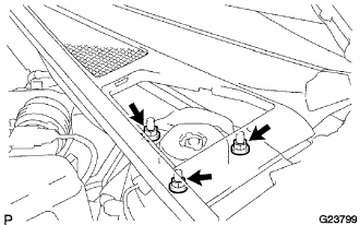 |
Install the 3 nuts to the upper side of the front shock absorber with coil spring.
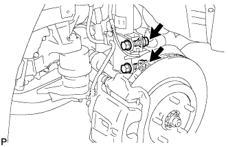 |
Install the 2 nuts to the lower side of the front shock absorber with coil spring.
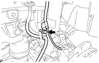 |
Install the front flexible hose No.2 and front speed sensor wire harness with the bolt.
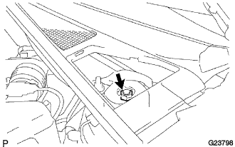 |
Fully tighten the lock nut.
| 7. INSTALL COWL TOP SILENCER PAD |
Engage the 5 claws to install the cowl top silencer pad.
| 8. INSTALL FRONT STABILIZER LINK ASSEMBLY |
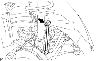 |
Install the front stabilizer link assembly with the nut.
| 9. INSTALL FRONT AXLE ASSEMBLY |
Install the front axle assembly to the front drive shaft assembly.
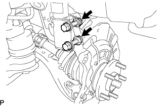 |
Install the front axle assembly to the front shock absorber assembly with the 2 bolts and nuts.
| 10. CONNECT FRONT SUSPENSION ARM SUB-ASSEMBLY LOWER NO.1 |
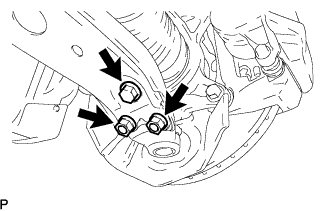 |
Install the lower ball joint to the front suspension arm sub-assembly lower with the bolt and 2 nuts.
| 11. CONNECT TIE ROD ASSEMBLY |
Install the tie rod end to the steering knuckle with the nut.
Install a new cotter pin.
| 12. INSTALL FRONT DISC |
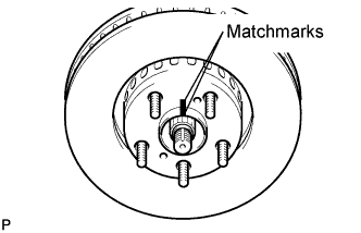 |
Align the matchmarks and install the front disc.
| 13. INSTALL FRONT DISC BRAKE CALIPER ASSEMBLY LH |
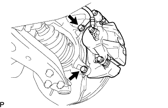 |
Install the front disc brake caliper assembly with the 2 bolts to the steering knuckle.
| 14. INSTALL FRONT AXLE HUB NUT |
Using a socket wrench (30 mm), install a new axle hub nut.
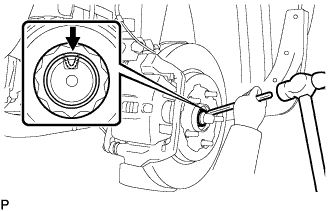 |
Using a chisel and hammer, stake the axle hub nut.
| 15. INSTALL SPEED SENSOR FRONT |
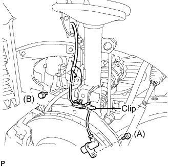 |
Install the speed sensor to the steering knuckle with the bolt.
Install the flexible hose and the speed sensor to the shock absorber with the bolt and set the clip of sensor on the knuckle.
| 16. ADD AND INSPECT HYBRID TRANSAXLE FLUID |
Fill oil.
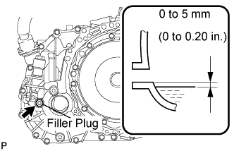 |
Check that the oil surface is within 5 mm (0.20 in.) from the lowest position of the inner surface of the differential filler plug opening.
Using a socket hexagon wrench 10 mm, temporarily tighten the filler plug and gasket.
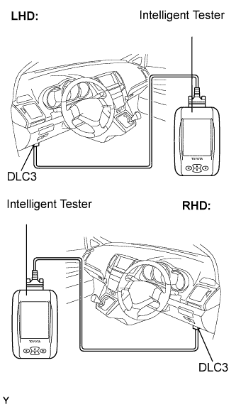 |
Connect the intelligent tester to the DLC3.
Turn the ignition switch to the ON position.
Select the inspection mode. (Click here)
On the tester, enter the following menus: Powertrain / Hybrid Control / Active test / Inspection Mod 1.
Turn the ignition switch to the ON position and turn the tester on.
Using a socket hexagon wrench 10 mm, remove the filler plug and gasket.
Fill oil.
|
Check that the oil surface is within 5 mm (0.20 in.) from the lowest position of the inner surface of the differential filler plug opening.
Check for leaks if the quantity of oil is low.
Using a socket hexagon wrench 10 mm, install the filler plug, and a new gasket.
| 17. INSPECT AND ADJUST FRONT WHEEL ALIGNMENT |
| 18. INSTALL ENGINE UNDER COVER NO.2 |
Install the 2 bolts and engine under cover No.2.
| 19. INSTALL ENGINE UNDER COVER NO.1 |
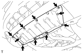 |
Install the 6 bolts, 2 screws, 2 clips and engine under cover.
| 20. CHECK ABS SPEED SENSOR SIGNAL |
