REAR TRACTION MOTOR > INSTALLATION |
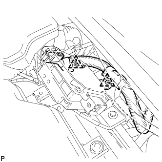
| 1. INSTALL EXTENSION WIRE ASSEMBLY |
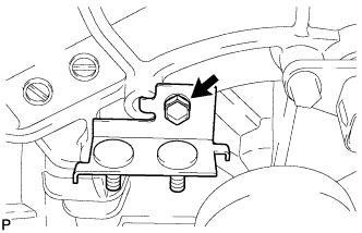 |
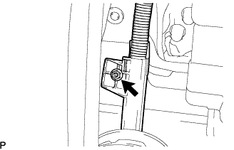
Install the wire harness clamp bracket with the bolt to the rear traction w/ transaxle motor.
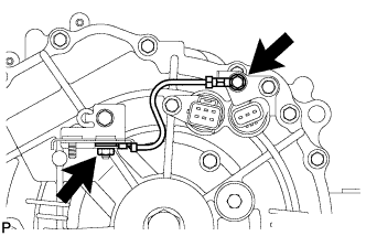 |
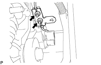
Install the wire harness clamp bracket and ground wire to the rear traction w/ transaxle motor with the bolt and nut.
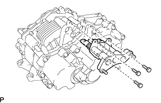 |
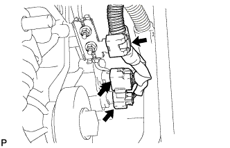
Install the extension wire with the 3 bolts to the rear traction w/ transaxle motor.
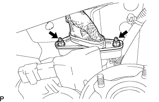
| 2. INSTALL FRONT DIFFERENTIAL SUPPORT ASSEMBLY |
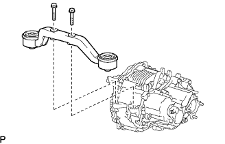 |
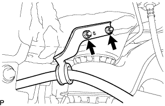
Install the front differential support assembly with the 2 bolts to the rear traction w/ transaxle motor.
| 3. INSTALL REAR TRACTION W/ TRANSAXLE MOTOR ASSEMBLY |
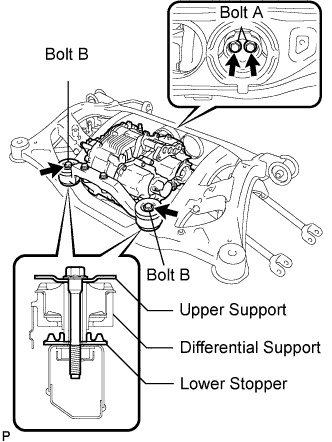 |
Place the lower stopper, differential support assembly FR w/ rear traction motor, and upper stopper in this order. Install them to the rear suspension member with the 4 bolts.
| 4. INSTALL REAR SUSPENSION MEMBER SUB-ASSEMBLY |
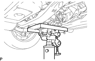 |
Slowly jack up the vehicle and install the rear suspension member w/ rear traction motor to the vehicle.
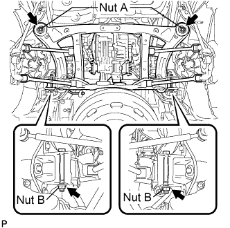 |
Install the rear suspension member to the vehicle with the 2 bolts and 4 nuts.
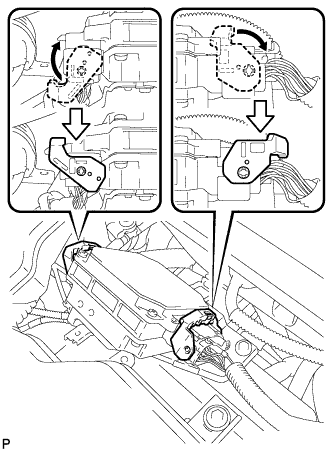
| 5. CONNECT NO.3 WIRE FRAME |
 |
Wear insulated gloves. Install the frame wire No.3 to the rear traction motor with the 2 nuts.
 |
Install the wire harness clamp to the vehicle with the nut.
 |
Install the ground cable to the rear traction motor with the nut.
 |
Connect the 2 connectors and clamp to the rear traction motor.
| 6. CONNECT PARKING BRAKE CABLE ASSEMBLY NO.3 |
 |
Install the parking brake No.3 cable assembly with the 2 nuts.
| 7. CONNECT PARKING BRAKE CABLE ASSEMBLY NO.2 |
| 8. INSTALL REAR DRIVE SHAFT ASSEMBLY LH |
Align the matchmarks.
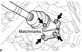 |
Install the rear drive shaft assembly with the 4 nuts and washers.
| 9. INSTALL REAR DRIVE SHAFT ASSEMBLY RH |
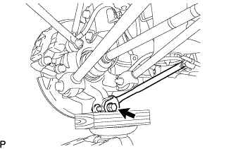
| 10. TEMPORARILY TIGHTEN REAR SUSPENSION ARM ASSEMBLY NO.2 LH |
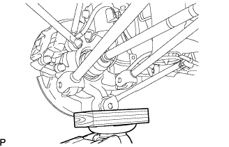 |
Jack up the rear axle carrier, placing a wooden block to avoid damage.
 |
Temporarily tighten the rear suspension arm assembly No.2 with the bolt and nut.
| 11. TEMPORARILY TIGHTEN REAR SUSPENSION ARM ASSEMBLY NO.2 RH |
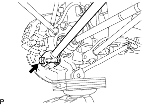
| 12. TEMPORARILY TIGHTEN REAR SUSPENSION ARM ASSEMBLY NO.1 LH |
 |
Temporarily tighten the rear suspension arm assembly No.1 with the bolt and nut.
| 13. TEMPORARILY TIGHTEN REAR SUSPENSION ARM ASSEMBLY NO.1 RH |
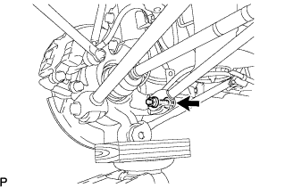
| 14. TEMPORARILY TIGHTEN REAR STRUT ROD ASSEMBLY |
 |
Temporarily tighten the strut rod assembly rear with the bolt and nut.
| 15. STABILIZE SUSPENSION |
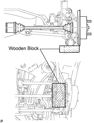 |
Jack up the rear axle carrier, placing a wooden block to avoid damage. Apply load to the suspension so that the rear drive shaft assembly is horizontally positioned.
| 16. FULLY TIGHTEN REAR SUSPENSION ARM ASSEMBLY NO.2 LH |
|
Fully tighten the bolt.
| 17. FULLY TIGHTEN REAR SUSPENSION ARM ASSEMBLY NO.2 RH |
| 18. FULLY TIGHTEN REAR SUSPENSION ARM ASSEMBLY NO.1 LH |
|
Fully tighten the bolt.
| 19. FULLY TIGHTEN REAR SUSPENSION ARM ASSEMBLY NO.1 RH |
| 20. FULLY TIGHTEN REAR STRUT ROD ASSEMBLY |
|
Fully tighten the bolt.
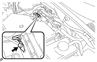
| 21. CONNECT HEIGHT CONTROL SENSOR |
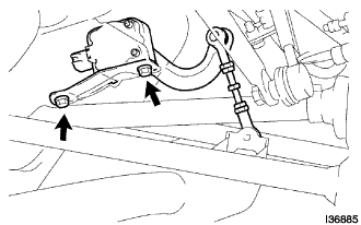 |
Install the height control sensor with the 2 bolts.
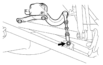 |
Install the height control sensor link with the "torx" nut.
Connect the connector.
| 22. INSTALL REAR AXLE SHAFT LH NUT |
Using a socket wrench (30mm), install a new rear axle shaft nut.
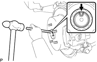 |
Using a chisel and hammer, stake the rear axle shaft nut.
| 23. INSTALL REAR AXLE SHAFT RH NUT |
| 24. INSPECT AND ADJUST REAR WHEEL ALIGNMENT |
| 25. INSTALL EXHAUST PIPE ASSEMBLY |
| 26. INSTALL POWER STEERING ECU BRACKET |
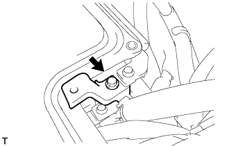 |
Install the power steering ECU bracket with the bolt to the w/ converter inverter assembly.
| 27. CONNECT INVERTER RESERVE TANK SUB-ASSEMBLY |
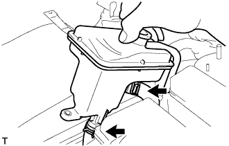 |
Connect the 2 water hoses with the 2 clamps to the inverter reserve tank sub-assembly.
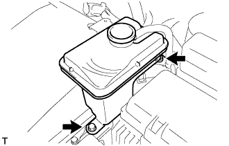 |
Install the inverter reserve tank with the 2 bolts to the w/ converter inverter assembly.
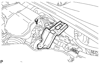
| 28. INSTALL POWER STEERING ECU ASSEMBLY |
 |
Install the power steering ECU assembly with the 2 bolts.
 |
Connect the 2 wire harness clamps to the power steering ECU assembly.
 |
Connect the 2 power steering ECU assembly connectors and securely lock the connectors.
 |
Install the ground cable terminal to the power steering ECU assembly with the bolt.
| 29. INSTALL INVERTER BRACKET NO.5 |
 |
Install the inverter bracket No.5 with the bolt.
| 30. INSTALL REAR WHEELS |
| 31. CONNECT CABLE TO NEGATIVE BATTERY TERMINAL |
| 32. CHECK HIGH VOLTAGE CABLE CONNECTION |
|
Make sure that the frame wire No.3 is securely installed with the nuts.
| 33. INSTALL SERVICE PLUG GRIP |
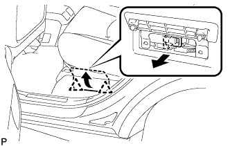 |
Wear insulation gloves, then insert the service plug.
Push down on the grip to lock.
Close the battery service hole cover.
| 34. INSTALL ENGINE ROOM SIDE COVER LH |
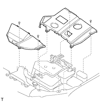 |
Fit the clips and install the engine room side LH cover.
| 35. ADD AND INSPECT HYBRID TRANSAXLE FLUID |
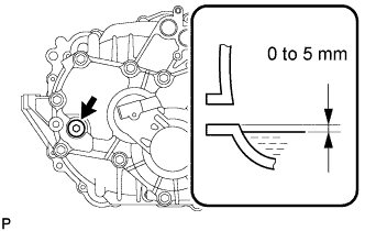 |
Check that the oil surface is within 5 mm (0.20 in.) from the lowest position of the inner surface of the transaxle filler plug opening.
Check for leaks if the quantity of oil is low.
Using a socket hexagon wrench 10 mm, install the filler plug and a new gasket.
| 36. INSPECT EXHAUST GAS LEAK |
| 37. HEADLIGHT AIM ONLY |
| 38. PERFORM INITIALIZATION |
