TRANSAXLE CONTROL CABLE ASSEMBLY > INSTALLATION |
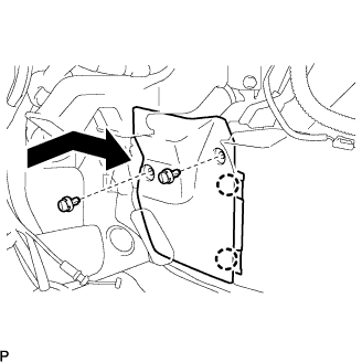
| 1. INSTALL TRANSMISSION CONTROL CABLE ASSEMBLY |
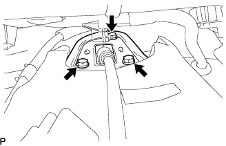 |
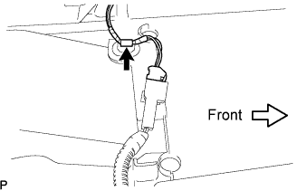
Pull in the control cable to the body.
Install the 3 bolts.
| 2. INSTALL AIR BAG SENSOR ASSEMBLY CENTER |
Check that the ignition switch is off.
Check that the battery negative (-) terminal is disconnected.
 |
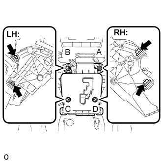
Temporarily install the center airbag sensor assembly with the 3 bolts.
Tighten the 3 bolts to the specified torque.
Check that there is no looseness in the installation parts of the center airbag sensor assembly.
Connect the 3 connectors to the center airbag sensor assembly.
Check that the waterproof sheet is properly set.
| 3. INSTALL AIR DUCT REAR NO.2 |
| 4. INSTALL AIR DUCT REAR NO.1 |
| 5. INSTALL CONSOLE BOX DUCT NO.1 |
| 6. INSTALL SHIFT LEVER |
 |
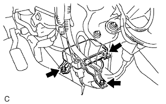
Install the floor shift assembly with the 4 nuts.
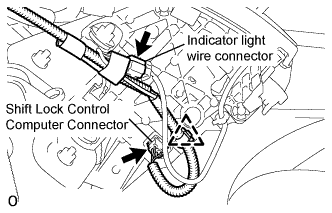 |
Install the pattern select switch connector, the shift lock control computer connector and the indicator light wire connector.
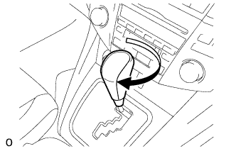
| 7. CONNECT TRANSMISSION CONTROL CABLE ASSEMBLY |
In the cabin
Connect the socket of the transmission control cable assembly to the shift lever assembly.
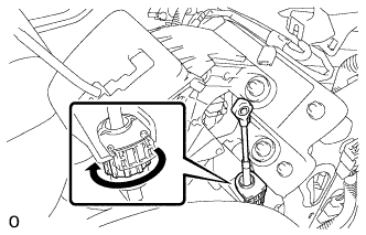 |
Turn the socket of the transmission control cable assembly clockwise and install the stopper cap.
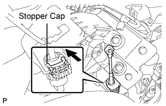 |
Push the stopper cap to the socket as shown in the illustration.
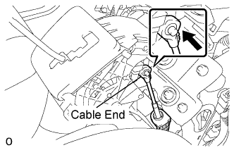 |
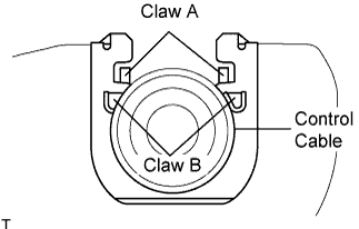
Connect the control cable end to the shift lever assembly.
Move the shift lever to the N position.
In the engine compartment
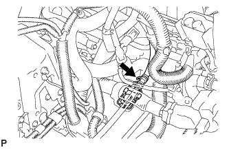 |
Connect the control cable to the control cable clamp.
Move the control shaft lever to the N position.
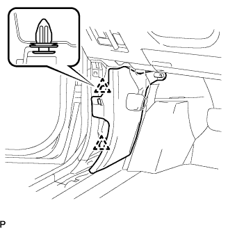
Install a new clip to the control bracket.
 |
Install the control cable to the control bracket.
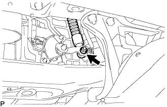 |
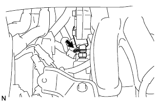
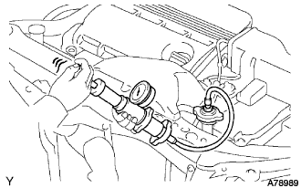
Temporarily install the control cable to the control shaft lever with the nut.
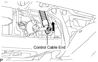 |
Lightly push up the control cable end.
Release your hand from the control cable end and then fully tighten the nut.
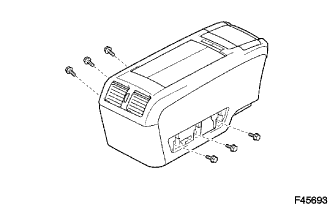
| 8. INSTALL CONSOLE COVER LOWER |
 |
Connect the connector to the console cover lower.
Install the console cover lower with the 2 screws.
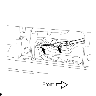
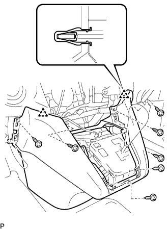
| 9. INSTALL CONSOLE BOX ASSEMBLY |
 |
Connect each of the clamp and the connector.
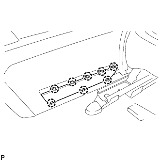
 |
Keeping the rear console box pulled in the rear direction of the vehicle, install the 6 bolts from the left and right sides.
 |
Connect the console box lock control cable assembly and install the rear console box.
| 10. INSTALL CONSOLE BOX HOLE COVER NO.2 |
| 11. INSTALL CONSOLE BOX HOLE COVER |
 |
Slide the front seat assemblies RH and LH forward.
Slide the rear console box fully to the back end and install the console box hole cover.
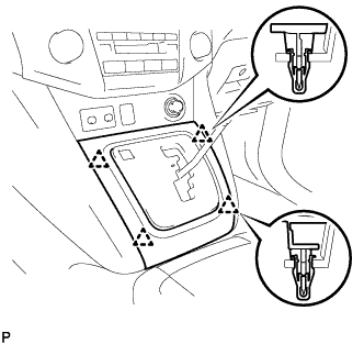
| 12. INSTALL INSTRUMENT PANEL FINISH PANEL LOWER CENTER |
 |
Engage the 2 clips.
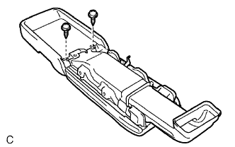
Install the 7 screws <C> and the instrument panel finish panel lower center.
| 13. INSTALL FLOOR CARPET COVER CENTER RH |
| 14. INSTALL FLOOR CARPET COVER CENTER LH |
 |
Slide the floor carpet cover center LH to the rear of the vehicle, and engage the 2 claws to the instrument panel finish panel lower center at the floor carpet cover center LH.
Install the 2 clips and the floor carpet cover center LH.
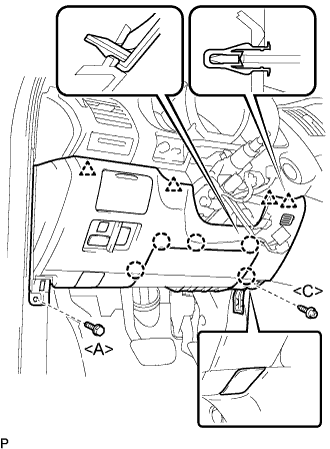
| 15. INSTALL GLOVE COMPARTMENT DOOR ASSEMBLY |
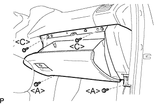 |
Connect the connectors.
Install the 2 bolts <A>, the 2 screws <C>, and the glove compartment door assembly.
| 16. INSTALL INSTRUMENT PANEL UNDER COVER SUB-ASSEMBLY NO.2 |
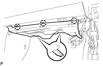 |
Connect the connectors.
Engage the 3 claws and install the instrument panel No.2 under cover sub-assembly.
| 17. INSTALL COWL SIDE TRIM SUB-ASSEMBLY LH |
 |
Install the 2 clips and the cowl side trim sub-assembly LH.
| 18. INSTALL FRONT DOOR SCUFF PLATE LH |
 |
Connect the connector. (w/ illumination scuff plate)
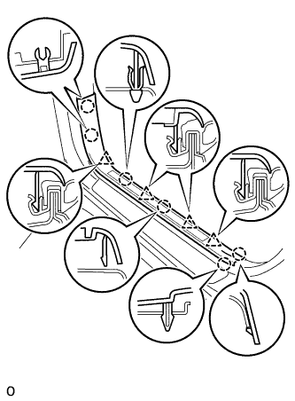
Engage the 6 claws and 4 clips, and install the front door scuff plate.
| 19. INSTALL INSTRUMENT PANEL FINISH PANEL SUB-ASSEMBLY LOWER |
 |
Connect the connectors.
Engage the 5 claws and the 4 clips.
Connect the hood lock control cable assembly.
Install the bolt <A>, the screw <C>, and the instrument panel finish panel sub-assembly lower.
| 20. INSTALL COWL SIDE TRIM SUB-ASSEMBLY RH |
| 21. INSTALL FRONT DOOR SCUFF PLATE RH |
| 22. INSTALL INSTRUMENT PANEL FINISH PANEL LOWER |
 |
Connect the connectors.
Engage the 2 clips and install the instrument panel finish panel lower.
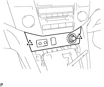
| 23. INSTALL CONSOLE PANEL UPPER FRONT |
 |
Engage the 4 clips and install the console panel upper front.
| 24. INSTALL SHIFT LEVER KNOB |
 |
Install the shift lever knob.
| 25. INSTALL INTAKE AIR SURGE TANK |
Install a new gasket to the intake air surge tank.
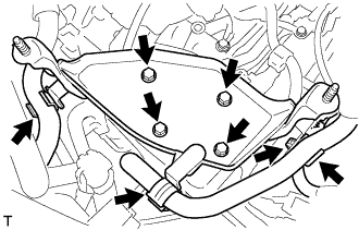
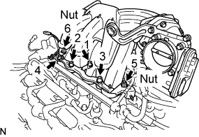 |
Using a socket hexagon wrench 8 mm, install the intake manifold with the 4 bolts and 2 nuts . Using several steps, tighten the bolts and nuts uniformly in the sequence shown in the illustration.
Connect the ground cable connector.
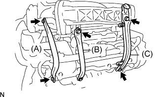 |
Install the surge tank stay No. 2 (A) with the 2 bolts.
Install the surge tank stay No. 1 (B) with the 2 bolts.
Install the engine hunger No. 1 (C) with the 2 bolts.
 |
Connect the ventilation hose.
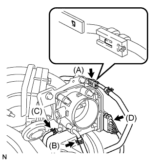 |
Connect the fuel vapor feed hose (A).
Connect the water by-pass hose No.3 (B).
Connect the water by-pass hose No.2 (C).
Connect the throttle motor connector (D).
| 26. INSTALL EMISSION CONTROL VALVE SET |
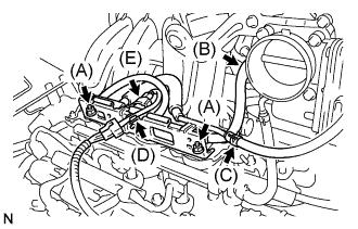 |
Install the emission control valve set with the 2 nuts (A).
Connect the fuel vapor feed hose No.2 (B).
Connect the fuel vapor feed hose No.1 (C).
Connect the wire harness clamp (D).
Connect the VSV connector (E).
| 27. INSTALL INVERTER BRACKET NO.1 |
 |
Install the 4 bolts and inverter bracket.
Install the harness clamp and hose clamp.
| 28. INSTALL W/CONVERTER INVERTER ASSEMBLY |
| 29. ADD COOLANT (Hybrid side) |
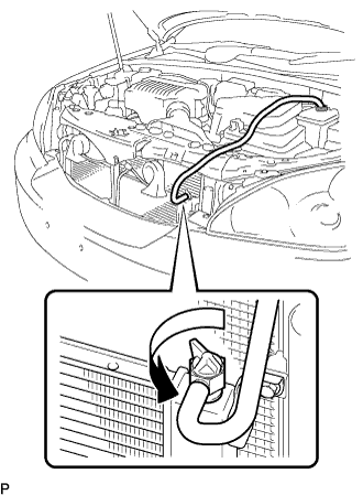 |
Loosen the bleeder plug shown in the illustration and connect a hose.
Add coolant from the reserve tank.
 |
Add coolant until the level of coolant in the hose attached to the bleeder plug reaches the same level as the FULL line of the reserve tank.
When using the intelligent tester:
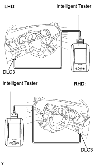 |
Connect the intelligent tester to the DLC3.
Turn the ignition switch to the ON position.
Select the inspection mode (Click here).
On the tester, enter the following menus: Powertrain / Hybrid Control / Active test / Water Pump.
Keep the coolant at the FULL level in the reserve tank to compensate for the drop in coolant level when the air bleeds.
When not using the intelligent tester:
Put the vehicle into the READY-on state. [*1]
Turn the ignition switch off and add coolant to the FULL level because the coolant level drops as the air bleeds. [*2]
Repeat steps [*1] and [*2] until air bleeding from the coolant system is completed.
When the air is completely bled from the coolant system, tighten the plug.
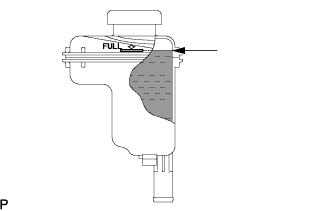 |
Add coolant to the FULL mark of the reserve tank.
| 30. ADD COOLANT (Engine side) |
Tighten the lower drain plug of the radiator.
Loosen the upper drain plug of the radiator.
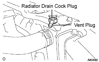 |
Install a vinyl tube to the vent plug located on the upper drain plug.
Fill the radiator with engine coolant until the vinyl tube is filled with the coolant.
Tighten the upper drain plug.
Install the radiator cap securely.
Fill the radiator reservoir tank with coolant.
Warm up the engine.
Stop the engine and wait until the coolant cools down.
Remove the radiator cap and check the coolant level inside the radiator.
If the coolant level is below the full level, perform the steps from (a) through (j) and repeat the operation until the coolant level stays the full level.
Recheck the coolant level inside the radiator reservoir tank. If it is below the full level, add the coolant.
| 31. CHECK FOR COOLANT LEAKS (Hybrid side) |
| 32. CHECK FOR COOLANT LEAKS (Engine side) |
 |
Fill the radiator with coolant and attach a radiator cap tester.
Warm up the engine.
Using a radiator cap tester, increase the pressure inside the radiator to 118 kPa (1.2 kgf*cm, 17 psi), and check that the pressure does not drop.
If the pressure drops, check the hoses, radiator and water pump for leaks. If no external leaks are found, check the heater core, cylinder block and cylinder head.
| 33. INSPECT SHIFT LEVER POSITION |
Apply the parking brake.
Lock the wheels with chocks to secure the vehicle.
Put the vehicle into the READY-on state.
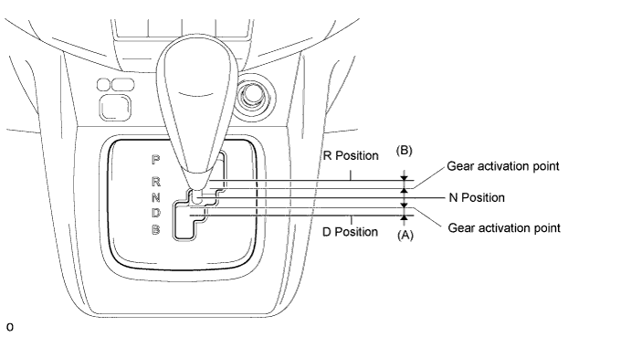
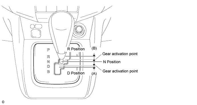
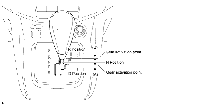
Move the shift lever to the D position and release the brake pedal.
Slowly move the shift lever to the N position and measure moving distance (A) of the shift lever from the original point to the gear activation point.
Move the shift lever to the R position and release the brake pedal.
Slowly move the shift lever to the N position and measure moving distance (B) of the shift lever from the original point to the vehicle activation point.
Check that moving distances (A) and (B) shown in the illustration are almost the same.
| 34. ADJUST SHIFT LEVER POSITION |
If moving distance (A) is shorter than (B) [*1]:
Move the shift lever to the N position.
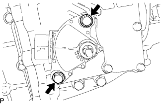 |
Loosen the 2 bolts.
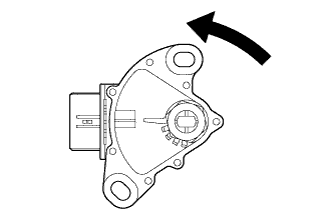 |
Slightly turn the park/neutral position switch counterclockwise.
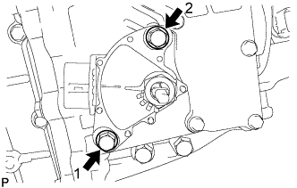 |
Tighten the 2 bolts in the order shown in the illustration.
Recheck the shift lever position.
If moving distance (B) is shorter than (A) [*2]:
Move the shift lever to the N position.
|
Loosen the 2 bolts.
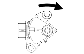 |
Slightly turn the park/neutral position switch clockwise.
|
Tighten the 2 bolts in the order shown in the illustration.
Recheck the shift lever position.
| 35. INSPECT SHIFT LEVER OPERATION |
While moving the shift lever from the N position to each position, check that the lever moves smoothly and that the shift position indicator comes on properly according to the shift lever position.
Put the vehicle into the READY-on state and check the following:
When the shift lever is moved to the D position, the vehicle moves forward.
When the shift lever is moved to the R position, the buzzer sounds and the vehicle moves in reverse.
| 36. INSTALL ENGINE UNDER COVER NO.1 |
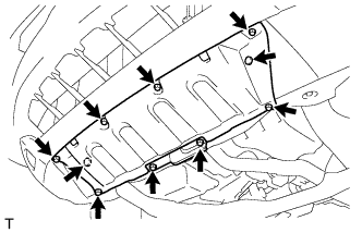 |
Install the 6 bolts, 2 screws, 2 clips and engine under cover.
| 37. PERFORM INITIALIZATION |
